Subsystem
Placement
Rules
If
the
system
was
disassembled
to
reduce
weight
to
enable
movement
to
its
installation
site,
the
following
subsystem
placement
rules
must
be
followed
when
reassembling
the
components
into
the
rack.
Placement
of
processor
subsystems,
I/O
subsystems,
and
IBFs
in
the
rack
must
conform
to
the
following
rules:
v
Processor
subsystems
and
I/O
drawers
must
be
populated
in
a
specified
drawer
order
in
a
rack.
v
Processor
subsystems
must
be
installed
in
each
frame
cage
from
left
to
right
(facing
the
front
of
the
rack).
v
Drawer
locations
for
the
bulk
power
enclosure
and
IBFs
are
fixed.
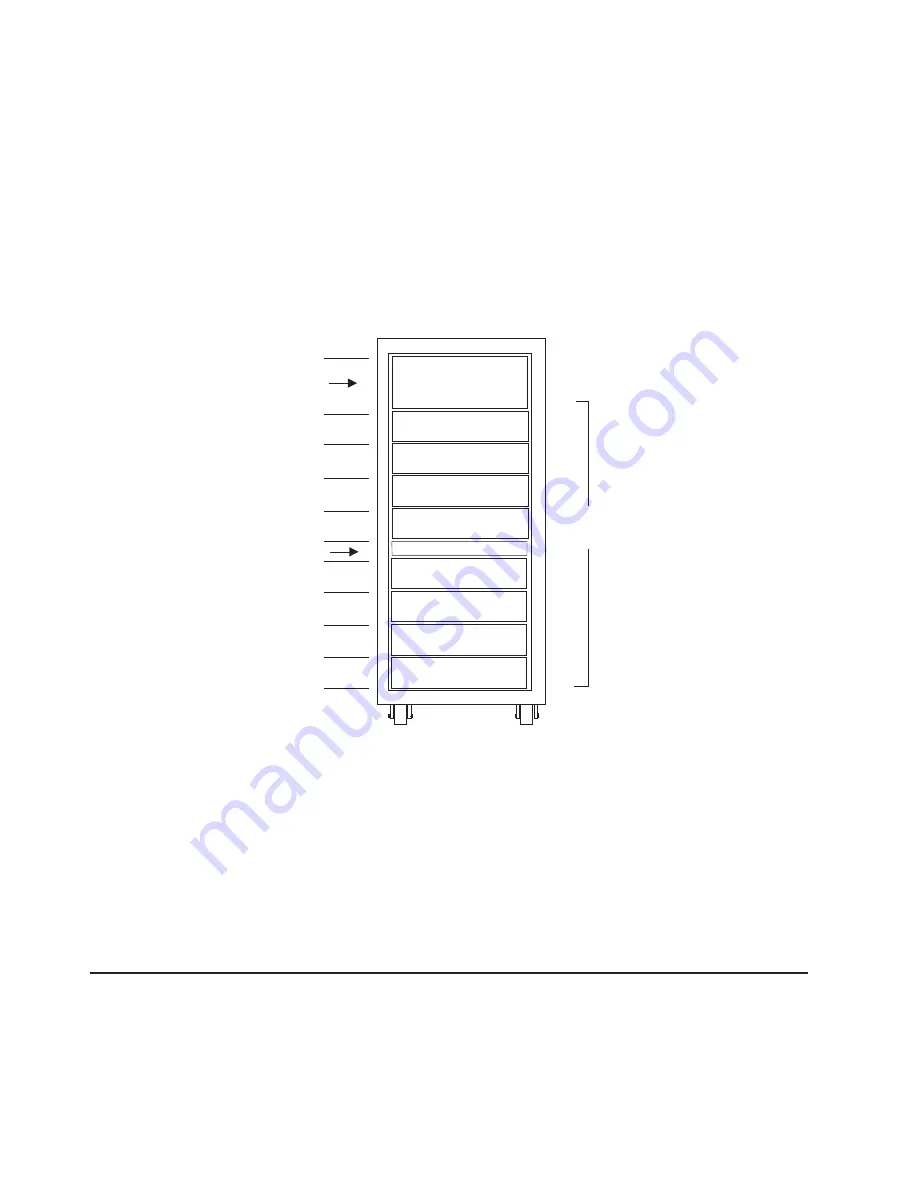
The
following
illustration
shows
the
order
for
populating
drawers
in
a
rack.
Order for
Populating
Drawers
3
2
1
8
4
5
6
7
Reserved
for Bulk
Power Enclosure
Reserved
for IBF
01
05
09
13
17
19
23
27
31
35
EIA
Reference
System
Cables
Various
cables
connect
the
power,
processor
subsystem(s),
battery,
I/O
subsystems,
and
the
HMCs.
These
include:
v
Universal
Power
Interface
Controller
(UPIC)
cables
are
the
power
cables
for
the
processor
subsystem(s)
v
Remote
Input/Output
(RIO
or
RIO-2)
cables
are
the
cables
connecting
the
processor
subsystem(s)
with
the
I/O
subsystems
v
RS232
cables
connect
the
processor
subsystems
to
the
HMC
port
adapters.
The
connection
is
made
directly
in
small
configurations
or
through
remote
asynchronous
nodes
in
large
rack
configurations.
For
detailed
information
about
cables,
refer
to
Appendix
G,
“Cabling
Information,”
on
page
155.
Multiple
System
Configurations
The
system
configuration
may
vary.
Other
configurations
include
the
following:
v
Multiple
processor
subsystems
attached
to
one
HMC.
For
more
information
about
this
configuration,
see
“Install
and
Configure
an
8-Port
Asynchronous
Adapter”
on
page
24
and
“Install
and
Configure
an
128-Port
Asynchronous
Adapter”
on
page
25.
v
Multiple
IBF
units,
I/O
subsystems,
Bulk
Power
Jumpers
(BPJ),
and
processor
subsystems.
130
Eserver
pSeries
655
Installation
Guide
Summary of Contents for pseries 655
Page 1: ...pSeries 655 Installation Guide SA38 0616 03 ERserver...
Page 2: ......
Page 3: ...pSeries 655 Installation Guide SA38 0616 03 ERserver...
Page 14: ...xii Eserver pSeries 655 Installation Guide...
Page 22: ...6 Eserver pSeries 655 Installation Guide...
Page 54: ...38 Eserver pSeries 655 Installation Guide...
Page 101: ...2 1 1 Top of Cassette 2 Handle Chapter 4 Installation and Removal Procedures 85...
Page 125: ...1 Metal EMC Shield 2 Adapter Bracket Chapter 4 Installation and Removal Procedures 109...
Page 128: ...112 Eserver pSeries 655 Installation Guide...
Page 132: ...116 Eserver pSeries 655 Installation Guide...
Page 156: ...140 Eserver pSeries 655 Installation Guide...
Page 204: ...188 Eserver pSeries 655 Installation Guide...
Page 211: ......
Page 212: ...Part Number 80P3836 Printed in USA February 2004 SA38 0616 03 1P P N 80P3836...


