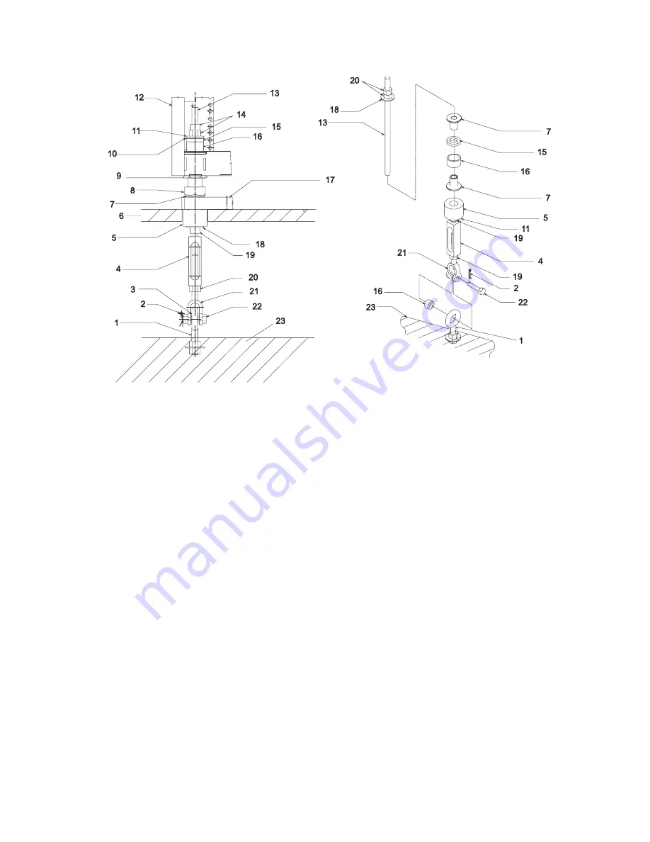
1
Floor
Eyebolt
9
Jam
Nut
17
Weight
Distribution
Plate
2
Pin
10
Plastic
Bushing
18
Washer
3
Spacer
11
Washer
19
-
20
Nut
4
Toggle
Block
12
Frame
21
Turnbuckle
Jaw
5
Rubber
Bushing
13
Threaded
Rod
22
Shaft
6
Raised
Floor
14
Nut
23
Floor
7
Plastic
Bushing
15
Thick
Washer
8
Leveler
16
Spacer
Notes:
a.
The
four
eyebolts
required
in
the
installation
is
supplied
and
installed
in
the
concrete
floor
by
the
customer.
b.
The
difference
between
the
turnbuckle
assemblies
for
the
low-raised
floor
and
the
high-raised
floor
is
the
length
of
the
turnbuckle:
v
The
short
turnbuckle
assembly
(part
number
11P4755)
is
used
for
a
24.13
cm
(9-1/2
in.)
to
29.8
cm
(11-3/4
in.)
raised
floor.
v
The
long
turnbuckle
assembly
(part
number
11P4756)
is
used
for
a
29.8
cm
(11-3/4
in.)
to
40.6
cm
(16
in.)
raised
floor.
3.
Place
the
spacer
inside
the
floor
eyebolt,
and
position
the
floor
eyebolt
between
the
lower
jaw
of
the
toggle
block.
4.
Install
the
shaft,
nut
and
pin
(if
applicable),
and
spacer.
5.
Turn
the
toggle
block
until
the
tip
of
lower
jaw
is
approximately
2.54
cm
(1
in.)
inside
the
toggle
block.
6.
Remove
threaded
rod,
rubber
bushing,
plastic
housing
and
washers
from
the
turnbuckle
assembly.
7.
Install
the
floor
tile
and
place
the
stabilizer
plate
on
the
floor
tile.
8.
Line
up
the
holes
in
the
floor
tiles
with
the
holes
in
the
stabilizer
bar.
9.
Move
the
system
frame
so
that
the
frame
leveler
is
located
over
the
prepared
floor
tiles
holes.
148
Eserver
pSeries
655
Installation
Guide
Summary of Contents for pseries 655
Page 1: ...pSeries 655 Installation Guide SA38 0616 03 ERserver...
Page 2: ......
Page 3: ...pSeries 655 Installation Guide SA38 0616 03 ERserver...
Page 14: ...xii Eserver pSeries 655 Installation Guide...
Page 22: ...6 Eserver pSeries 655 Installation Guide...
Page 54: ...38 Eserver pSeries 655 Installation Guide...
Page 101: ...2 1 1 Top of Cassette 2 Handle Chapter 4 Installation and Removal Procedures 85...
Page 125: ...1 Metal EMC Shield 2 Adapter Bracket Chapter 4 Installation and Removal Procedures 109...
Page 128: ...112 Eserver pSeries 655 Installation Guide...
Page 132: ...116 Eserver pSeries 655 Installation Guide...
Page 156: ...140 Eserver pSeries 655 Installation Guide...
Page 204: ...188 Eserver pSeries 655 Installation Guide...
Page 211: ......
Page 212: ...Part Number 80P3836 Printed in USA February 2004 SA38 0616 03 1P P N 80P3836...


