1
2
3
4
5
6
7
8
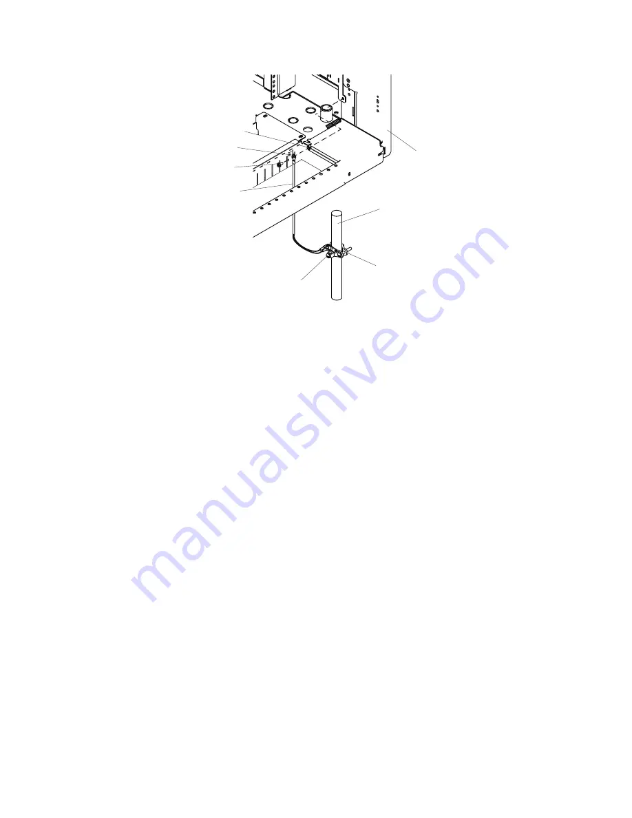
Right Rear of Rack
1
Screw
on
Ground
Clamp
(for
tightening
the
clamp)
5
Lockwasher
(install
if
supplied)
2
Grounding
Clamp
6
Lug
on
Ground
Strap
3
Metal
Floor
Pedestal
7
Screw
(for
attaching
lug
to
the
rack)
4
Bottom
Right
Side
of
the
Rear
of
the
Rack
8
Ground
Strap
b.
Position
the
ground
strap
clamp
(part
number
5457808)
around
a
grounded
floor
pedestal.
c.
Using
a
screwdriver,
tighten
the
ground
strap
clamp
screw
to
secure
the
clamp
to
the
floor
pedestal.
d.
Attach
the
other
end
of
the
ground
strap
to
the
ground
strap
clamp
on
the
floor
pedestal.
5.
If
no
other
service
procedures
are
being
performed,
close
the
rack
door.
Non-Raised
Floor
Environments
Determine
if
the
frame
ground
straps
are
required
(refer
to
the
Attention
in
“Install
the
Frame
Ground
Straps”
on
page
152)
and
“Signal
Integrity”
on
page
152.
If
your
installation
is
not
using
a
grounded-raised
floor,
and
your
servers
are
connected
to
an
9076
SP
Switch2
clustered
environment,
all
attached
server
frames
in
your
environment
must
be
independently
grounded
to
the
switch
frame.
Use
the
following
information
to
help
you
install
multiple
systems
to
the
9076
SP
Switch2
switch
frame
in
a
clustered
environment:
v
Order
grounding
straps
by
calling
the
IBM
Quality
Hotline
at
1-800-IBM-LINE
and
requesting
Part
Number
44P3695,
Grounding
Kit.
Each
kit
contains
one
ground
strap
and
the
required
hardware
to
make
a
single
connection
between
a
server
and
a
9076
SP
Switch2,
so
order
one
kit
for
each
server
that
is
connected
to
the
switch.
v
An
IBM
service
representative
will
install
the
grounding
straps
by
using
instructions
that
are
provided
with
the
grounding
kits.
Each
server
frame
must
be
directly
connected
to
a
9076
SP
Switch2
frame.
154
Eserver
pSeries
655
Installation
Guide
Summary of Contents for pseries 655
Page 1: ...pSeries 655 Installation Guide SA38 0616 03 ERserver...
Page 2: ......
Page 3: ...pSeries 655 Installation Guide SA38 0616 03 ERserver...
Page 14: ...xii Eserver pSeries 655 Installation Guide...
Page 22: ...6 Eserver pSeries 655 Installation Guide...
Page 54: ...38 Eserver pSeries 655 Installation Guide...
Page 101: ...2 1 1 Top of Cassette 2 Handle Chapter 4 Installation and Removal Procedures 85...
Page 125: ...1 Metal EMC Shield 2 Adapter Bracket Chapter 4 Installation and Removal Procedures 109...
Page 128: ...112 Eserver pSeries 655 Installation Guide...
Page 132: ...116 Eserver pSeries 655 Installation Guide...
Page 156: ...140 Eserver pSeries 655 Installation Guide...
Page 204: ...188 Eserver pSeries 655 Installation Guide...
Page 211: ......
Page 212: ...Part Number 80P3836 Printed in USA February 2004 SA38 0616 03 1P P N 80P3836...


