Note:
Because
of
the
number
of
cables
routed
on
the
inside
of
the
rack,
screws
are
difficult
to
locate.
2
1
3
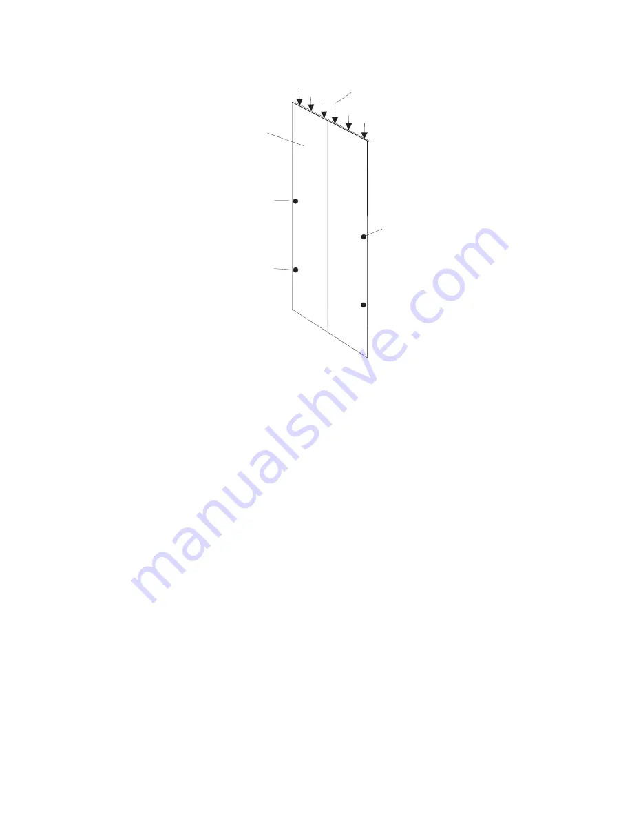
EIA 25
EIA 13
1
Outside
of
Side
Cover
2
Locations
of
Screws
at
the
Top
of
the
Cover
3
Locations
of
Screws
on
the
Side
of
the
Cover
(approximate
EIA
locations)
3.
Remove
the
(3)
screws
at
the
top
of
the
frame
on
each
side
of
the
frame
side
cover.
The
use
of
a
stepladder
is
recommended
for
this
procedure.
4.
With
all
the
screws
removed,
rock
the
cover
to
the
right
from
the
top.
There
are
features
built
into
the
cover
that
lock
it
behind
the
left
cover,
and
these
features
must
be
clear
before
you
can
lift
the
cover
from
the
frame.
To
make
lifting
the
cover
easier,
tilt
the
top
of
the
cover
away
from
the
frame
after
the
feature
tabs
have
cleared
the
left
cover.
5.
To
remove
the
left
side
covers,
perform
Steps
2
through
4.
6.
With
all
the
screws
removed
from
the
cover,
tilt
the
top
of
the
cover
away
from
the
frame
and
lift
off.
174
Eserver
pSeries
655
Installation
Guide
Summary of Contents for pseries 655
Page 1: ...pSeries 655 Installation Guide SA38 0616 03 ERserver...
Page 2: ......
Page 3: ...pSeries 655 Installation Guide SA38 0616 03 ERserver...
Page 14: ...xii Eserver pSeries 655 Installation Guide...
Page 22: ...6 Eserver pSeries 655 Installation Guide...
Page 54: ...38 Eserver pSeries 655 Installation Guide...
Page 101: ...2 1 1 Top of Cassette 2 Handle Chapter 4 Installation and Removal Procedures 85...
Page 125: ...1 Metal EMC Shield 2 Adapter Bracket Chapter 4 Installation and Removal Procedures 109...
Page 128: ...112 Eserver pSeries 655 Installation Guide...
Page 132: ...116 Eserver pSeries 655 Installation Guide...
Page 156: ...140 Eserver pSeries 655 Installation Guide...
Page 204: ...188 Eserver pSeries 655 Installation Guide...
Page 211: ......
Page 212: ...Part Number 80P3836 Printed in USA February 2004 SA38 0616 03 1P P N 80P3836...


