v
The power LED on each compute node flashes slowly to indicate that the compute node is connected
to power and is ready to be turned on.
v
The power LED on the top of rack switch (if applicable).
Make sure that the following LEDs on the back of the system are lit:
v
The dc power and ac power LEDs on each power supply.
v
The power LED on each I/O module.
For more information about identifying your system's components, see the Overview section for your
offering.
About this task
Cable a system to the Chassis Management Module (CMM) to perform a verification check, and access
your IBM Storwize V7000 to ensure that it is functioning. To perform an installation verification check, do
the following:
Procedure
Do you have only one chassis?
1.
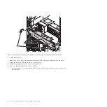
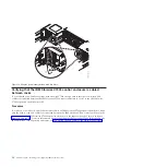
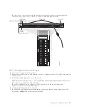
If you have one chassis, install the IBM BNT SFP (RJ45) transceiver (
B
in Figure 16 on page 17). This
SFP transceiver is included in the ship group. Install the transceiver in I/O module slot 1, port 6.
2.
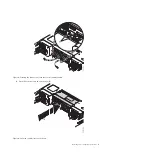
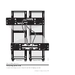
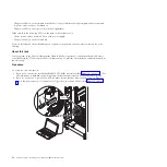
If you do not have a top of rack switch, connect a device that has browser access and an Ethernet
port to the transceiver on I/O module slot 1, port 6 on the switch chassis (
A
16
PureFlex System: Installing and configuring IBM PureFlex System
Summary of Contents for PureFlex System
Page 1: ...PureFlex System Installing and configuring IBM PureFlex System GI11 9880 02...
Page 2: ......
Page 3: ...PureFlex System Installing and configuring IBM PureFlex System GI11 9880 02...
Page 6: ...iv PureFlex System Installing and configuring IBM PureFlex System...
Page 34: ...22 PureFlex System Installing and configuring IBM PureFlex System...
Page 44: ...32 PureFlex System Installing and configuring IBM PureFlex System...
Page 45: ......
Page 46: ...Part Number 00L5196 Printed in USA GI11 9880 02 1P P N 00L5196...

