background image

This information is for planning purposes only. The information herein is subject to change before the
products described become available.

This information contains examples of data and reports used in daily business operations. To illustrate
them as completely as possible, the examples include the names of individuals, companies, brands, and
products. All of these names are fictitious and any similarity to the names and addresses used by an
actual business enterprise is entirely coincidental.

If you are viewing this information in softcopy, the photographs and color illustrations may not appear.

The drawings and specifications contained herein shall not be reproduced in whole or in part without the
written permission of the manufacturer.

The manufacturer has prepared this information for use with the specific machines indicated. The
manufacturer makes no representations that it is suitable for any other purpose.

The manufacturer's computer systems contain mechanisms designed to reduce the possibility of
undetected data corruption or loss. This risk, however, cannot be eliminated. Users who experience
unplanned outages, system failures, power fluctuations or outages, or component failures must verify the
accuracy of operations performed and data saved or transmitted by the system at or near the time of the
outage or failure. In addition, users must establish procedures to ensure that there is independent data
verification before relying on such data in sensitive or critical operations. Users should periodically check
the manufacturer's support websites for updated information and fixes applicable to the system and
related software.

Ethernet connection usage restriction

This product is not intended to be connected directly or indirectly by any means whatsoever to interfaces
of public telecommunications networks.

Trademarks

IBM, the IBM logo, and ibm.com are trademarks or registered trademarks of International Business
Machines Corp., registered in many jurisdictions worldwide. Other product and service names might be
trademarks of IBM or other companies. A current list of IBM trademarks is available on the web at
Copyright and trademark information at www.ibm.com/legal/copytrade.shtml.

Electronic emission notices

When attaching a monitor to the equipment, you must use the designated monitor cable and any
interference suppression devices supplied with the monitor.

Class A Notices

The following Class A statements apply to the IBM servers that contain the POWER7

®

processor and its

features unless designated as electromagnetic compatibility (EMC) Class B in the feature information.

Federal Communications Commission (FCC) statement

Note:

This equipment has been tested and found to comply with the limits for a Class A digital device,

pursuant to Part 15 of the FCC Rules. These limits are designed to provide reasonable protection against
harmful interference when the equipment is operated in a commercial environment. This equipment
generates, uses, and can radiate radio frequency energy and, if not installed and used in accordance with
the instruction manual, may cause harmful interference to radio communications. Operation of this
equipment in a residential area is likely to cause harmful interference, in which case the user will be
required to correct the interference at his own expense.

24

PureFlex System: Installing and configuring IBM PureFlex System

Summary of Contents for PureFlex System

Page 1: ...PureFlex System Installing and configuring IBM PureFlex System GI11 9880 02...

Page 2: ......

Page 3: ...PureFlex System Installing and configuring IBM PureFlex System GI11 9880 02...

Page 4: ...n the safety and environmental notices included with the system This edition applies to the IBM PureFlex System and to all subsequent releases and modifications until otherwise indicated in new editio...

Page 5: ...ng the IBM Storwize V7000 shipping brackets 6 Verifying that the IBM Storwize V7000 control enclosure is cabled between racks 12 Connecting power cords 13 Performing a verification check 15 Completing...

Page 6: ...iv PureFlex System Installing and configuring IBM PureFlex System...

Page 7: ...ct The documentation contains the safety information in your national language with references to the U S English source Before using a U S English publication to install operate or service this produ...

Page 8: ...will be attached to this product to properly wired outlets v When possible use one hand only to connect or disconnect signal cables v Never turn on any equipment when there is evidence of fire water...

Page 9: ...e customer to ensure that the outlet is correctly wired and grounded to prevent an electrical shock CAUTION v Do not install a unit in a rack where the internal rack ambient temperatures will exceed t...

Page 10: ...port the weight of the loaded rack cabinet Refer to the documentation that comes with your rack cabinet for the weight of a loaded rack cabinet v Verify that all door openings are at least 760 x 230 m...

Page 11: ...This product might contain one or more of the following devices CD ROM drive DVD ROM drive DVD RAM drive or laser module which are Class 1 laser products Note the following information v Do not remove...

Page 12: ...ing information for NEBS Network Equipment Building System GR 1089 CORE The following comments apply to the IBM servers that have been designated as conforming to NEBS Network Equipment Building Syste...

Page 13: ...have Serial Attached SCSI SAS cables that where shipped with the system chassis you must plug them into the appropriate ports Small form factor pluggable SFP transceivers should be taken from the shi...

Page 14: ...9 SW2 p19 Serial Chassis SW A2RR 90Y9340 43X0510 2x user installed when if needed debug Does not include FC EFPT Connect to Customer Management Network For more information see Setting up your IBM Fle...

Page 15: ...y takes over shipment Follow the unpacking instructions that came with the system User task Contact IBM Lab Services Team if purchased to tell them to go ahead with the next step User task IBM Lab Ser...

Page 16: ...step 12 You meet with an IBM Services Team representative to complete the system configuration 13 An IBM Services Team representative cables a laptop to the management network to access the Managemen...

Page 17: ...tion plate and the front stabilizer bracket on the front of the rack cabinet The recirculation prevention plate uses the same four screws and holes in the rack as the front stabilizer bracket a Align...

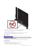
Page 18: ...brackets If present remove the brackets that protect the IBM Storwize V7000 controller during shipping Figure 4 Installing the recirculation plate and front stabilizer bracket Figure 5 Installing the...

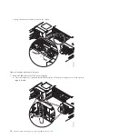
Page 19: ...ol canisters to the shipping bracket Note Ensure that you do not clip any cables 2 Remove the two screws B that attach the bracket to the rack See Figure 7 on page 8 3 Loosen the three tension screws...

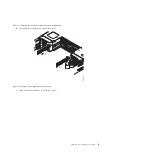
Page 20: ...the shipping bracket and remove it from the rack 6 Reseat the IBM Storwize V7000 control canisters a Press the latches A on the unseated IBM Storwize V7000 control canister to access the control cani...

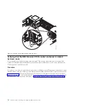
Page 21: ...b Push the canister into the enclosure B Figure 8 Pressing the latches to access the control canister handle Figure 9 Push the canister into the enclosure Installing and configuring the system 9...

Page 22: ...at the IBM Storwize V7000 power supplies a Press the latches A on the unseated IBM Storwize V7000 power supply to access the power supply handle Figure 10 Snap the latches back into place 10 PureFlex...

Page 23: ...into the enclosure B c Snap the enclosure latches C back into place Figure 11 Pressing the latches to access the power supply handle Figure 12 Push the power supply into the enclosure Installing and c...

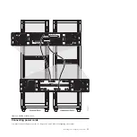
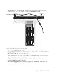
Page 24: ...has an IBM Storwize V7000 expansion enclosure make sure the rack to rack SAS cables are connected between the IBM Storwize V7000 control enclosure in the system rack to the IBM Storwize V7000 expansio...

Page 25: ...Connecting power cords You must connect the power cords to the power source before configuring the system Figure 14 Cabling between racks Installing and configuring the system 13...

Page 26: ...en the fasteners For more information about identifying parts or cables see the appropriate information for your configuration v For the IBM PureFlex System Express see Identifying hardware components...

Page 27: ...le you must perform a verification check For more information see Performing a verification check Performing a verification check Check to ensure that all of your hardware components are present and f...

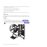
Page 28: ...Chassis Management Module CMM to perform a verification check and access your IBM Storwize V7000 to ensure that it is functioning To perform an installation verification check do the following Proced...

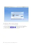
Page 29: ...re that you type https The s means that you will be using the Secure Sockets Layer SSL when you communicate with the CMM If you have additional chassis type https 192 168 93 102 for the second chassis...

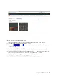
Page 30: ...sword is Passw0rd 9 Cancel out of the Initial Setup Wizard 10 Click System Status 11 Hover over each component to ensure that it is functioning properly Figure 18 CMM sign in window 18 PureFlex System...

Page 31: ...ngle IBM Storwize V7000 chassis with no top of rack switch connect it directly to port 1 on the upper controller 15 Verify that your IBM Storwize V7000 storage is functioning Open a different browser...

Page 32: ...ou have a second IBM Storwize V7000 type 192 168 93 217 service in a different browser window Complete steps 16 on page 19 and 17 for this second IBM Storwize V7000 19 You may now disconnect the devic...

Page 33: ...to do the following after the IBM Service Team representative leaves your site v Change passwords v Create users v Create partitions or virtual servers v Install operating systems For more information...

Page 34: ...22 PureFlex System Installing and configuring IBM PureFlex System...

Page 35: ...or changes in the product s and or the program s described in this publication at any time without notice Any references in this information to websites not owned by the manufacturer are provided for...

Page 36: ...and fixes applicable to the system and related software Ethernet connection usage restriction This product is not intended to be connected directly or indirectly by any means whatsoever to interfaces...

Page 37: ...he laws of the Member States relating to electromagnetic compatibility IBM cannot accept responsibility for any failure to satisfy the protection requirements resulting from a non recommended modifica...

Page 38: ...e s Republic of China Declaration This is a Class A product In a domestic environment this product may cause radio interference in which case the user may need to perform practical action Electromagne...

Page 39: ...Erweiterungskomponenten von Fremdherstellern ohne Empfehlung von IBM gesteckt eingebaut werden EN 55022 Klasse A Ger te m ssen mit folgendem Warnhinweis versehen werden Warnung Dieses ist eine Einrich...

Page 40: ...st harmful interference in a residential installation This equipment generates uses and can radiate radio frequency energy and if not installed and used in accordance with the instructions may cause h...

Page 41: ...of EU Council Directive 2004 108 EC on the approximation of the laws of the Member States relating to electromagnetic compatibility IBM cannot accept responsibility for any failure to satisfy the pro...

Page 42: ...Handb chern beschrieben zu installieren und zu betreiben Des Weiteren d rfen auch nur von der IBM empfohlene Kabel angeschlossen werden IBM bernimmt keine Verantwortung f r die Einhaltung der Schutzan...

Page 43: ...cial Use You may reproduce distribute and display these publications solely within your enterprise provided that all proprietary notices are preserved You may not make derivative works of these public...

Page 44: ...32 PureFlex System Installing and configuring IBM PureFlex System...

Page 45: ......

Page 46: ...Part Number 00L5196 Printed in USA GI11 9880 02 1P P N 00L5196...

Reviews: