background image

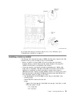
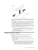
6. Touch the static-protective package that contains the DIMM to any unpainted

metal surface on the outside of the server. Then, remove the DIMM from the
package.

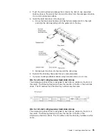
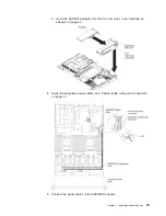
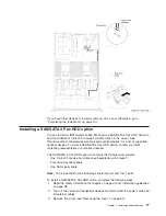
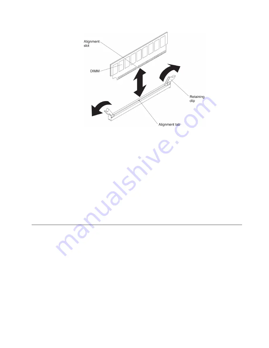
7. Turn the DIMM so that the alignment slot align correctly with the alignment tab.

8. Insert the DIMM into the connector by aligning the edges of the DIMM with the

slots at the ends of the DIMM connector (see “System-board optional devices
connectors” on page 38 for the locations of the DIMM connectors).

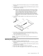
9. Firmly press the DIMM straight down into the connector by applying pressure on

both ends of the DIMM simultaneously. The retaining clips snap into the locked
position when the DIMM is firmly seated in the connector.

Note:

If there is a gap between the DIMM and the retaining clips, the DIMM
has not been correctly inserted; open the retaining clips, remove the
DIMM, and then reinsert it.

If you have other devices to install or remove, do so now. Otherwise, go to
“Completing the installation” on page 101.

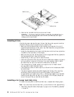
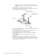
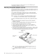
Replacing a PCI riser-card assembly

Note:

PCI riser-card brackets must be installed even if you do not install an
adapter.

To replace a PCI riser-card assembly, complete the following steps:

1. Read the safety information that begins on page vii and the “Installation

guidelines” on page 38.

2. Turn off the server and peripheral devices and disconnect the power cords and

all external cables.

Note:

When you disconnect the power source from the server, you lose the
ability to view the LEDs because the LEDs are not lit when the power
source is removed. Before you disconnect the power source, make a
note of which LEDs are lit, including the LEDs that are lit on the
operation information panel, on the light path diagnostics panel, and

Chapter 2. Installing optional devices

65

Summary of Contents for Redboks System x3550 M4

Page 1: ...IBM System x3550 M4 Type 7914 Installation and User s Guide...

Page 2: ......

Page 3: ...IBM System x3550 M4 Type 7914 Installation and User s Guide...

Page 4: ...tices and User Guide documents on the IBM Documentation CD and the Warranty Information document The most recent version of this document is available at http www ibm com supportportal Fifth Edition O...

Page 5: ...oard LEDs 37 System board optional devices connectors 38 Installation guidelines 38 System reliability guidelines 40 Working inside the server with the power on 40 Handling static sensitive devices 40...

Page 6: ...s 109 Passwords 113 Using the Boot Manager 115 Starting the backup server firmware 115 Using the integrated management module II 115 Obtaining the IP address for the IMM2 117 Logging on to the web int...

Page 7: ...nd Class A statement 131 European Union EMC Directive conformance statement 131 Germany Class A statement 131 VCCI Class A statement 132 Japan Electronics and Information Technology Industries Associa...

Page 8: ...vi IBM System x3550 M4 Type 7914 Installation and User s Guide...

Page 9: ...ety Information Avant d installer ce produit lisez les consignes de s curit Vor der Installation dieses Produkts die Sicherheitshinweise lesen Prima di installare questo prodotto leggere le Informazio...

Page 10: ...formation document For example if a caution statement is labeled Statement 1 translations for that caution statement are in the Safety Information document under Statement 1 Be sure to read all cautio...

Page 11: ...isconnect signal cables v Never turn on any equipment when there is evidence of fire water or structural damage v Disconnect the attached power cords telecommunications systems networks and modems bef...

Page 12: ...um battery replace it only with the same module type made by the same manufacturer The battery contains lithium and can explode if not properly used handled or disposed of Do not v Throw or immerse in...

Page 13: ...radiation There are no serviceable parts inside the device v Use of controls or adjustments or performance of procedures other than those specified herein might result in hazardous radiation exposure...

Page 14: ...rical current supplied to the device The device also might have more than one power cord To remove all electrical current from the device ensure that all power cords are disconnected from the power so...

Page 15: ...ltage current and energy levels are present inside any component that has this label attached There are no serviceable parts inside these components If you suspect a problem with one of these parts co...

Page 16: ...es This server is suitable for use on an IT power distribution system whose maximum phase to phase voltage is 240 V under any distribution fault condition Statement 27 CAUTION Hazardous moving parts a...

Page 17: ...on document that comes with the server The server contains IBM X Architecture technologies which help increase performance and reliability For more information see What your server offers on page 8 an...

Page 18: ...able you can download them from the IBM website The server might have features that are not described in the documentation that comes with the server and the documentation might be updated occasionall...

Page 19: ...microprocessor v 32 MB of RAM v Adobe Acrobat Reader 3 0 or later or xpdf which comes with Linux operating systems Using the Documentation Browser Use the Documentation Browser to browse the contents...

Page 20: ...mation about the server including how to set up and cabling the server how to install supported optional devices and how to configure the server The following documentation also comes with the server...

Page 21: ...ment are also in the multilingual Safety Information document which is on the IBM System x Documentation CD Each statement is numbered for reference to the corresponding statement in your language in...

Page 22: ...Slot 2 supports half length full height cards PCI Express 3 0 x8 PCI Express 3 0 x16 two microprocessors installed PCI X 64 bit 133 MHz Video controller integrated into IMM2 v Matrox G200eR2 Note The...

Page 23: ...FoD RAID 5 50 and SED Self Encrypting Drive upgrade v A ServeRAID M5110 SAS SATA adapter that provides RAID 0 1 and 10 Optional upgrade RAID 5 50 512 MB Cache with optional FoD RAID 6 60 and SED upgr...

Page 24: ...output system BIOS compatibility support UEFI replaces the BIOS and defines a standard interface between the operating system platform firmware and external devices UEFI compliant System x servers are...

Page 25: ...ates and stores data on two pairs of DIMMs within two channels simultaneously If a failure occurs the memory controller switches from the primary pair of memory DIMMs to the backup pair of DIMMs For m...

Page 26: ...l height cards Slot 2 can support PCI Express or PCI X adapters through an optional PCI riser card See Installing an adapter on page 67 for detailed information v Active Energy Manager The IBM Active...

Page 27: ...bility Three important computer design features are reliability availability and serviceability RAS The RAS features help to ensure the integrity of the data that is stored in the server the availabil...

Page 28: ...v Systems management monitoring through the Inter Integrated Circuit IC protocol bus v Upgradeable POST Unified Extensible Firmware Interface UEFI diagnostics IMM2 firmware and read only memory ROM re...

Page 29: ...ttp publib boulder ibm com infocenter director v6r1x index jsp topic director_6 1 fqm0_main html and the Systems Management web page at http www ibm com systems management which presents an overview o...

Page 30: ...is LED is lit it indicates that the optional DVD drive is in use v Operator information panel This panel contains controls and LEDs that provide information about the status of the server For informat...

Page 31: ...ually locate the server among the others servers v Check log LED When this yellow LED is lit it indicates that a system error has occurred Check the error log for additional information See the Proble...

Page 32: ...e the system error LED flashes once every 2 seconds until the problem is corrected the server is restarted or a new problem occurs By placing the system error LED indicator in Remind mode you acknowle...

Page 33: ...t a power supply error Complete the following steps to correct the problem 1 Check the power supply with a lit yellow LED see AC power supply LEDs on page 23 2 Make sure that the power supplies are se...

Page 34: ...nd 5000008 lndocid SERV CALL NMI A nonmaskable interrupt has occurred or the NMI button was pressed 1 Check the system error log for information about the error 2 Restart the server CONFIG CONFIG PS A...

Page 35: ...to make sure that they are compatible with each other see Installing a second microprocessor and heat sink on page 79 for additional information about microprocessor requirements and use the Setup ut...

Page 36: ...eseat the failing fan which is indicated by a lit LED near the fan connector on the system board 2 Replace the failing fan see Installing a hot swap fan assembly on page 93 BOARD An error has occurred...

Page 37: ...with the integrated management module II IMM2 The IMM2 can take control of the shared serial port to redirect serial traffic using Serial over LAN SOL v USB connectors Connect a USB device such as a U...

Page 38: ...es that the power supply is supplying adequate dc power to the system During typical operation both the ac and dc power LEDs are lit For any other combination of LEDs see the Problem Determination and...

Page 39: ...or IMM2 web interface to light this LED remotely v System error LED When this LED is lit it indicates that a system error has occurred An LED on the light path diagnostics panel is also lit to help is...

Page 40: ...ctions in Light path diagnostics LEDs on page 17 4 If the OVER SPEC LED on the light path diagnostics is not lit check the error LEDs on the system board and the IMM2 error messages Follow steps in th...

Page 41: ...the dc power source 1 Check the dc power to the server 2 Make sure that the power cord is connected to a functioning power source 3 Restart the server If the error remains check the power supply LEDs...

Page 42: ...EDs on page 17 4 If the OVER SPEC LED on the light path diagnostics is not lit check the error LEDs on the system board and the IMM2 error messages Follow steps in the Power problems under the Trouble...

Page 43: ...an ac power source but is not turned on the operating system does not run and all core logic except for the integrated management module II IMM2 is shut down however the server can respond to request...

Page 44: ...ower switch on the power supply do not turn off the electrical current supplied to the device The device also might have more than one power cord To remove all electrical current from the device ensur...

Page 45: ...v The integrated management module II IMM2 can turn off the server as an automatic response to a critical system failure Chapter 1 The System x3550 M4 server 29...

Page 46: ...30 IBM System x3550 M4 Type 7914 Installation and User s Guide...

Page 47: ...y with the newly installed devices 3 Save the DSA log as a file and send it to IBM For information about transferring data and logs see http publib boulder ibm com infocenter toolsctr v1r0 index jsp t...

Page 48: ...nents The following illustration shows the major components in the server The illustrations in this document might differ slightly from your hardware 32 IBM System x3550 M4 Type 7914 Installation and...

Page 49: ...System board internal connectors The following illustration shows the internal connectors on the system board Chapter 2 Installing optional devices 33...

Page 50: ...System board external connectors The following illustration shows the external connectors on the system board 34 IBM System x3550 M4 Type 7914 Installation and User s Guide...

Page 51: ...Clears the real time clock RTC registry JP2 UEFI boot backup jumper v Pins 1 and 2 Normal default Loads the primary server firmware ROM page v Pins 2 and 3 Loads the secondary backup server firmware R...

Page 52: ...t position after the power on password in overridden Changing the position of this switch does not affect the administrator password check if an administrator password is set See Passwords on page 113...

Page 53: ...System board LEDs The following illustration shows the light emitting diodes LEDs on the system board Chapter 2 Installing optional devices 37...

Page 54: ...that you are installing are supported For a list of supported optional devices for the server see http www ibm com systems info x86servers serverproven compat us v Read the safety information that be...

Page 55: ...y object To avoid straining the muscles in your back lift by standing or by pushing up with your leg muscles v Make sure that you have an adequate number of properly grounded electrical outlets for th...

Page 56: ...e installed the fourth and sixth fans when you installed the second microprocessor option Working inside the server with the power on Attention Static electricity that is released to internal server c...

Page 57: ...ds This drains static electricity from the package and from your body v Remove the device from its package and install it directly into the server without setting down the device If it is necessary to...

Page 58: ...42 IBM System x3550 M4 Type 7914 Installation and User s Guide...

Page 59: ...The following illustration shows the internal routing and connectors for the 3 5 inch simple swap hard disk drives SATA signal and power cables Chapter 2 Installing optional devices 43...

Page 60: ...ows the internal routing and connectors for the 3 5 inch hot swap hard disk drives SAS SATA signal power and configuration cables with the SAS SATA adapter installed 44 IBM System x3550 M4 Type 7914 I...

Page 61: ...The following illustration shows the internal routing and connectors for the SAS SATA signal power and configuration cables with the SAS SATA adapter installed Chapter 2 Installing optional devices 45...

Page 62: ...The following illustration shows the internal routing and connectors for the RAID battery cables with the SAS SATA adapter installed 46 IBM System x3550 M4 Type 7914 Installation and User s Guide...

Page 63: ...The following illustration shows the internal routing and connectors for the server models with one 2 5 inch simple swap hard disk drives Chapter 2 Installing optional devices 47...

Page 64: ...e connector release tab and then disconnect the cable from the connector on the system board Do not disconnect the cable by using excessive force 2 Follow the optical drive cable routing as the illust...

Page 65: ...le v To remove the operator information panel cable slightly press the cable toward the fan cage then pull to remove the cable from the connector on the system board Pulling the cable out of the conne...

Page 66: ...e front USB and video cables on the system board press evenly on the cables Pressing on one side of the cable might cause damage to the cable or connector Removing the cover Important Before you insta...

Page 67: ...he server has been installed in a rack slide the server out from the rack enclosure 4 Pull up firmly on the blue latch on the top in the center of the front of the server of the cover and slide the co...

Page 68: ...that come with the drive to determine whether you have to set any switches or jumpers on the drive If you are installing a SAS or SATA hard disk drive be sure to set the SAS or SATA ID for that device...

Page 69: ...that drive is faulty and must be replaced If the green hard disk drive activity LED is flashing the drive is being accessed Note If the server is configured for RAID operation using a ServeRAID adapt...

Page 70: ...to set any switches or jumpers on the drive If you are installing a SATA device be sure to set the SATA ID for that device v You can install up to three 3 5 inch simple swap SATA hard disk drives in t...

Page 71: ...ed earlier 7 If you are installing additional simple swap hard disk drives do so now IDs for 2 5 inch simple swap hard disk drives The simple swap drive ID that is assigned to each drive is printed on...

Page 72: ...ion information panel on the light path diagnostics panel and LEDs inside the server on the system board then see the Problem Determination and Service Guide for information about how to solve the pro...

Page 73: ...oducts contain an embedded Class 3A or Class 3B laser diode Note the following Laser radiation when open Do not stare into the beam do not view directly with optical instruments and avoid direct expos...

Page 74: ...e optical drive bay until the drive clicks into place 10 Connect the DVD drive cable see Installing the DVD drive cable on page 75 The following illustration shows the cable routing for the DVD drive...

Page 75: ...The server supports only industry standard double data rate 3 DDR3 800 1066 1333 or 1600 MHz PC3 6400 PC3 8500 PC3 10600 or PC3 12800 registered or unbuffered synchronous dynamic random access memory...

Page 76: ...DIMM R Registered DIMM RDIMM U Unbuffered DIMM with no ECC x64 bit primary data bus aa is the CAS latency in clocks at maximum operating frequency bb is the JEDEC SPD Revision Encoding and Additions l...

Page 77: ...IMMs 32 GB 768 GB v The UDIMM option that is available for the server is 4 GB The server supports a minimum of 4 GB and a maximum of 64 GB of system memory using UDIMMs v The RDIMM options that are av...

Page 78: ...he memory interface for each microprocessor can be populated in any order and have no matching requirements Table 7 Normal mode DIMM installation sequence Number of installed microprocessor DIMM conne...

Page 79: ...mory mirrored channel mode DIMM population sequence Number of DIMMs Number of installed microprocessor DIMM connector First pair of DIMMs 1 1 4 Second pair of DIMMs 1 9 12 Third pair of DIMMs 1 2 5 Fo...

Page 80: ...2 13 14 Eighth pair of DIMMs 2 16 17 Ninth pair of DIMMs 2 20 21 Tenth pair of DIMMs 2 23 24 Eleventh pair of DIMMs 2 19 22 Twelfth pair of DIMMs 2 15 18 Note DIMM connectors 3 6 7 10 15 18 19 and 22...

Page 81: ...n correctly inserted open the retaining clips remove the DIMM and then reinsert it If you have other devices to install or remove do so now Otherwise go to Completing the installation on page 101 Repl...

Page 82: ...move the adapter if one is present from the PCI riser card assembly 7 Set the adapter and the PCI riser card assembly aside 8 Install the adapter in the new PCI riser card assembly see Installing an a...

Page 83: ...n page 38 for the location of the internal SAS SATA RAID connector and SAS SATA RAID riser card slots You can replace the IBM ServeRAID SAS SATA adapter with an optional IBM ServeRAID SAS SATA adapter...

Page 84: ...want to install a PCI Express or PCI X adapter you must order the PCI riser card option PCI riser slot 1 This slot supports only low profile adapters PCI riser slot 2 This slot supports full height h...

Page 85: ...the riser card assembly Make sure that the adapter snaps into the riser card assembly securely Attention When you install an adapter make sure that the adapter is correctly seated in the riser card a...

Page 86: ...the system board complete the following steps 1 Read the safety information that begins on page vii and the Installation guidelines on page 38 2 Turn off the server and peripheral devices and disconne...

Page 87: ...red to as the SAS SATA adapter or the ServeRAID adapter 1 Read the safety information that begins on page vii and Installation guidelines on page 38 2 Turn off the server and peripheral devices and di...

Page 88: ...72 IBM System x3550 M4 Type 7914 Installation and User s Guide...

Page 89: ...e PCI riser cards see Installing an adapter on page 67 8 Route the backplane signal cables see Internal cable routing and connectors on page 41 9 Connect the signal cables to the SAS SATA adapter Chap...

Page 90: ...Connect the other signal cable that is attached to the drive backplane for drive bays 0 through 3 and connect it to the other connector port 0 on the adapter v ServeRAID M5110 adapter Take the signal...

Page 91: ...safety information that begins on page vii and Installation guidelines on page 38 2 Turn off the server and peripheral devices and disconnect the power cords 3 Remove the cover see Removing the cover...

Page 92: ...gn the cable connector with the connector on the rear of the DVD drive cage Press the cable connector into the optical drive cage connector and slide it to the left until it is firmly seated The follo...

Page 93: ...rketing representative or authorized reseller The SAS SATA 4 Pac HDD option kit contains the following components v One 2 5 inch hot swap hard disk drive backplane with bracket v Four drive bay filler...

Page 94: ...you install the backplane if that is easier for you 6 Connect the cables to the hard disk drive backplane 7 Connect the signal power and configuration cables to the system board Route the signal cable...

Page 95: ...ation on page 101 Installing a second microprocessor and heat sink The following notes describe the type of microprocessor that the server supports and other information that you must consider when yo...

Page 96: ...the same server model you do not have to install the microprocessor with lowest stepping level and features in microprocessor socket 1 v Both microprocessor voltage regulator modules are integrated o...

Page 97: ...r a Identify which release lever is labeled as the first release lever to open and open it b Open the second release lever on the microprocessor socket c Open the microprocessor retainer Attention Do...

Page 98: ...allation tool rests flush on the socket only if properly aligned d Twist the handle on the microprocessor tool counterclockwise to insert the microprocessor into the socket The microprocessor is keyed...

Page 99: ...e is present Store the socket cover in a safe place Attention When you handle static sensitive devices take precautions to avoid damage from static electricity For details about handling these devices...

Page 100: ...sor in the retention bracket thermal material side down d Press firmly on the heat sink e Rotate the heat sink retention module release lever to the closed position and hook it underneath the lock tab...

Page 101: ...ely 3 Use the cleaning pad to wipe the thermal grease from the bottom of the heat sink Note Make sure that all of the thermal grease is removed 4 Use a clean area of the cleaning pad to wipe the therm...

Page 102: ...r 200 240 V ac auto sensing v Power supplies in the server must be with the same power rating or wattage to ensure that the server will operate correctly For example you cannot mix 550 watt and 750 wa...

Page 103: ...move the power supply from the package and place it on a static protective surface 3 If you are installing a hot swap power supply into an empty bay remove the power supply filler from the power suppl...

Page 104: ...nd recognizes the newly installed devices and make sure that no error LEDs are lit 12 IBM Business Partners only Complete the additional steps in Instructions for IBM Business Partners on page 31 Inst...

Page 105: ...rimping tool to install the ring terminals to the power cord wires The ring terminals must be UL approved and must accommodate the wire that is described in the above mentioned note Statement 29 CAUTI...

Page 106: ...d in the following table when you install move or open covers on this product or attached devices To Connect To Disconnect 1 Turn OFF all power sources and equipment that is to be attached to this pro...

Page 107: ...nt to a properly grounded safety extra low voltage SELV source A SELV source is a secondary circuit that is designed so that normal and single fault conditions do not cause the voltages to exceed a sa...

Page 108: ...e static protective package that contains the hot swap power supply to any unpainted metal surface on the server then remove the power supply from the package and place it on a static protective surfa...

Page 109: ...the power supply is operating correctly 12 If you are replacing a power supply with one of a different wattage in the server apply the new power information label provided over the existing power inf...

Page 110: ...panel if it has not been removed already Keep the filler panel in a safe place 4 Touch the static protective package that contains the new fan to any unpainted metal surface on the server Then remove...

Page 111: ...dapter You can purchase one of the following dual port network adapters to add two additional network ports in the server To order a dual port network adapter option contact your IBM marketing represe...

Page 112: ...nabled after FoD installed v To download the latest version of drivers for iSCSI and FCoE from the IBM website complete the following steps 1 Go to http www ibm com support fixcentral 2 From the Produ...

Page 113: ...ector 2 see Replacing a PCI riser card assembly on page 65 5 Remove the adapter filler panel on the rear of the chassis if it has not been removed already 6 Touch the static protective package that co...

Page 114: ...h the chassis on the rear of the server An incorrectly seated adapter might cause damage to the system board or the adapter 9 Fasten the thumbscrew on the rear side of the chassis 10 Fasten the two ca...

Page 115: ...If you have other devices to install or remove do so now Otherwise go to Completing the installation on page 101 Installing a RAID adapter battery remotely in the server When you install any RAID ada...

Page 116: ...cable to the RAID adapter battery connector 6 Route the remote battery cable along the chassis Attention Make sure that the cable is not pinched and does not cover any connectors or obstruct any comp...

Page 117: ...lacing the air baffle on page 102 2 If you removed the server cover replace it see Replacing the cover on page 102 3 Install the server in the rack cabinet see the Rack Installation Instructions that...

Page 118: ...To replace the server cover complete the following steps 1 Make sure that all cables adapters and other components are installed and seated correctly and that you have not left loose tools or parts in...

Page 119: ...The following illustrations show the locations of the input and output connectors on the front of the server The following illustration shows the locations of the input and output connectors on the re...

Page 120: ...ts automatically so that you can save the new configuration settings Some optional devices have device drivers that you must install For information about installing device drivers see the documentati...

Page 121: ...nt module II on page 115 v Remote presence capability and blue screen capture The remote presence and blue screen capture feature are integrated into the Integrated Management Module II IMM2 The Integ...

Page 122: ...to start ServerGuide HII MegaRAID Storage Manager MSM MegaCLI Command Line Interface and IBM Director ServeRAID M5110 adapter MegaRAID BIOS Configuration Utility press Ctrl H to start pre boot CLI pre...

Page 123: ...stem type that are selectable during setup Note Features and functions can vary slightly with different versions of the ServerGuide program ServerGuide features Features and functions can vary slightl...

Page 124: ...erGuide program 1 After you have completed the setup process the operating system installation program starts You will need your operating system CD to complete the installation 2 The ServerGuide prog...

Page 125: ...r password a limited Setup utility menu is available 3 Select settings to view or change Setup utility menu choices The following choices are on the Setup utility main menu for the UEFI Depending on t...

Page 126: ...ormance and power utilization Legacy Support Select this choice to view or set legacy support Force Legacy Video on Boot Select this choice to force INT video support if the operating system does not...

Page 127: ...e the POST watchdog timer v POST Watchdog Timer Value Select this choice to view or set the POST loader watchdog timer value v Reboot System on NMI Select this choice to enable or disable restarting t...

Page 128: ...s Important If the system error LED on the front of the server is lit but there are no other error indications clear the IMM2 system event log Also after you complete a repair or correct an error clea...

Page 129: ...up utility menu If you set a power on password for a user and an administrator password for a system administrator you must type the power on password to complete the system startup A system administr...

Page 130: ...s Off While the server is turned off move switch 4 of the switch block SW3 to the On position to enable the power on password override You can then start the Setup utility and reset the power on passw...

Page 131: ...sition pins 1 and 2 Using the integrated management module II The integrated management module II IMM2 is the second generation of the IMM Unlike the first generation of IMM the IMM2 has three levels...

Page 132: ...ted by IPMI v Intelligent Platform Management Interface IPMI Specification V2 0 and Intelligent Platform Management Bus IPMB support v Invalid system configuration CNFG LED support v Serial over LAN S...

Page 133: ...static IP address of 192 168 70 125 2 On the Login page type the user name and password If you are using the IMM for the first time you can obtain the user name and password from your system administr...

Page 134: ...ture complete the following steps 1 Install the Integrated Management Module Advanced Upgrade 2 Turn on the server Note Approximately 20 to 40 seconds after the server is connected to power the power...

Page 135: ...he server support auto negotiation the controllers detect the data transfer rate 10BASE T 100BASE TX or 1000BASE T and duplex mode full duplex or half duplex of the network and automatically operate a...

Page 136: ...modify UEFI settings from the command line without the need to restart the system to access the Setup utility You can also use the ASU program to configure the optional remote presence features or ot...

Page 137: ...t fixcentral 3 From the Product family list select IBM Systems Director 4 From the Product list select IBM Systems Director 5 From the Installed version list select the latest version and click Contin...

Page 138: ...122 IBM System x3550 M4 Type 7914 Installation and User s Guide...

Page 139: ...rproven compat us to make sure that the hardware and software is supported by your IBM product v Go to http www ibm com supportportal to check for information to help you solve the problem v Gather th...

Page 140: ...ter information is http www ibm com systems bladecenter The address for IBM IntelliStation information is http www ibm com systems intellistation How to send Dynamic System Analysis data to IBM Use th...

Page 141: ...p www ibm com partnerworld and click Find Business Partners on the right side of the page For IBM support telephone numbers see http www ibm com planetwide In the U S and Canada call 1 800 IBM SERV 1...

Page 142: ...126 IBM System x3550 M4 Type 7914 Installation and User s Guide...

Page 143: ...S FOR A PARTICULAR PURPOSE Some states do not allow disclaimer of express or implied warranties in certain transactions therefore this statement may not apply to you This information could include tec...

Page 144: ...e capacity or communications volume MB stands for 1 000 000 bytes and GB stands for 1 000 000 000 bytes Total user accessible capacity can vary depending on operating environments Maximum internal har...

Page 145: ...tation of appropriate remedial measures to mitigate such environmental contamination Implementation of such remedial measures is a customer responsibility Table 14 Limits for particulates and gases Co...

Page 146: ...quipment is operated in a commercial environment This equipment generates uses and can radiate radio frequency energy and if not installed and used in accordance with the instruction manual may cause...

Page 147: ...Department M372 IBM Allee 1 71139 Ehningen Germany Telephone 49 7032 15 2941 Email lugi de ibm com Germany Class A statement Deutschsprachiger EU Hinweis Hinweis f r Ger te der Klasse A EU Richtlinie...

Page 148: ...0504 914 499 1900 Der verantwortliche Ansprechpartner des Herstellers in der EU ist IBM Deutschland GmbH Technical Regulations Abteilung M372 IBM Allee 1 71139 Ehningen Germany Telephone 49 7032 15 29...

Page 149: ...ipment for business Type A Sellers and users need to pay attention to it This is for any areas other than home Russia Electromagnetic Interference EMI Class A statement People s Republic of China Clas...

Page 150: ...134 IBM System x3550 M4 Type 7914 Installation and User s Guide...

Page 151: ...ation programs LSI Configuration Utility 106 configuration server updating 104 configuring RAID arrays 120 with ServerGuide 108 configuring the server 105 connecting cable 103 connector USB 14 video f...

Page 152: ...k drive 13 connectors 13 LED location 13 G gaseous contamination 6 129 getting help 123 grease thermal 84 guidelines options installation 38 system reliability 40 H handling static sensitive devices 4...

Page 153: ...em error 15 rear 23 system locator rear 23 LED errors dc power supply 25 LED system pulse 27 LEDs system board 37 legacy operating system requirement 108 License Agreement for Machine Code 4 Licenses...

Page 154: ...p power supplies 12 NIC 10 redundant array of independent disks RAID adapter 53 reliability 11 remind button 16 remote battery RAID adapter installing 99 remote presence feature using 117 removing air...

Page 155: ...Ethernet connector 21 systems management tool IBM Systems Director 12 T telephone numbers 125 temperature 6 thermal grease 84 ToolsCenter for System x and BladeCenter 39 trademarks 127 turning off th...

Page 156: ...140 IBM System x3550 M4 Type 7914 Installation and User s Guide...

Page 157: ......

Page 158: ...Part Number 00V9702 Printed in USA 1P P N 00V9702...

Reviews: