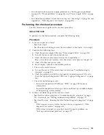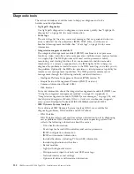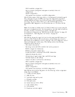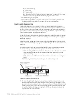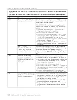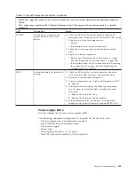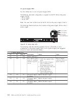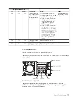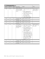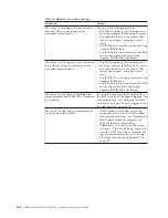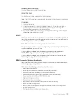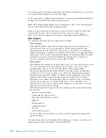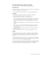
Table 14. Light path diagnostics panel LEDs (continued)
v
Follow the suggested actions in the order in which they are listed in the Action column until the problem is
solved.
v
If an action step is preceded by "(trained technician only)," that step must be performed only by a trained
technician.
LED
Description
Action
MEM
When only the MEM LED is lit, a
memory error has occurred.
Note:
Each time you install or remove a DIMM, you must
disconnect the server from the power source; then, wait 10
seconds before restarting the server.
If the CONFIG LED is not lit, the system might detect a
memory error. Complete the following steps to correct the
problem:
1.
Update the server firmware to the latest level (see
“Updating the firmware” on page 101).
2.
Reseat or swap the DIMMs with lit LED.
3.
Check the system-event log in the Setup utility or IMM
error messages. Follow steps indicated in Appendix B,
“UEFI/POST diagnostic codes,” on page 665 and
Appendix A, “Integrated management module II (IMM2)
error messages,” on page 335.
4.
Replace the failing DIMM (see “Removing a memory
module” on page 236 and “Installing a memory module”
on page 49).
MEM + CONFIG
When both the MEM and
CONFIG LEDs are lit, the
memory configuration is invalid.
If the MEM LED and the CONFIG LED are lit, check the
system-event log in the Setup utility or IMM2 error messages.
Follow steps indicated in Appendix B, “UEFI/POST
diagnostic codes,” on page 665 and Appendix A, “Integrated
management module II (IMM2) error messages,” on page
335.
TEMP
The system or the system
component temperature has
exceeded a threshold level. A
failing fan can cause the TEMP
LED to be lit.
1.
Make sure that the heat sink is seated correctly.
2.
Determine whether a fan has failed. If it has, replace it.
3.
Make sure that the room temperature is not too high. See
“Server features and specifications” on page 6 for the
server temperature information.
4.
Make sure that the air vents are not blocked.
5.
Make sure that the heat sink or the fan on the adapter, or
the optional network adapter is seated correctly. If the fan
has failed, replace it.
6.
For more information, go to http://www.ibm.com/
support/entry/portal/docdisplay?lndocid=SERV-CALL.
FAN
A fan has failed, is operating too
slowly, or has been removed. The
TEMP LED might also be lit.
1.
Check if your server installed with any of the adapters
mentioned in Table 25 on page 250 and Table 27 on page
262. If yes, make sure your server compile with the
configuration with six fans installed.
2.
Reseat the failing fan, which is indicated by a lit LED
near the fan connector on the system board.
3.
Replace the failing fan (see “Removing a hot-swap fan”
on page 266 and “Replacing a hot-swap fan” on page
267).
140
IBM System x3550 M4 Type 7914: Installation and Service Guide
Summary of Contents for Redboks System x3550 M4
Page 1: ...IBM System x3550 M4 Type 7914 Installation and Service Guide ...
Page 2: ......
Page 3: ...IBM System x3550 M4 Type 7914 Installation and Service Guide ...
Page 8: ...vi IBM System x3550 M4 Type 7914 Installation and Service Guide ...
Page 18: ...xvi IBM System x3550 M4 Type 7914 Installation and Service Guide ...
Page 42: ...24 IBM System x3550 M4 Type 7914 Installation and Service Guide ...
Page 118: ...100 IBM System x3550 M4 Type 7914 Installation and Service Guide ...
Page 214: ...196 IBM System x3550 M4 Type 7914 Installation and Service Guide ...
Page 352: ...334 IBM System x3550 M4 Type 7914 Installation and Service Guide ...
Page 702: ...684 IBM System x3550 M4 Type 7914 Installation and Service Guide ...
Page 798: ...780 IBM System x3550 M4 Type 7914 Installation and Service Guide ...
Page 802: ...784 IBM System x3550 M4 Type 7914 Installation and Service Guide ...
Page 811: ...Taiwan Class A compliance statement Notices 793 ...
Page 812: ...794 IBM System x3550 M4 Type 7914 Installation and Service Guide ...
Page 818: ...800 IBM System x3550 M4 Type 7914 Installation and Service Guide ...
Page 819: ......
Page 820: ... Part Number 00Y8006 Printed in USA 1P P N 00Y8006 ...


