v
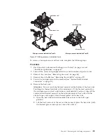
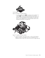
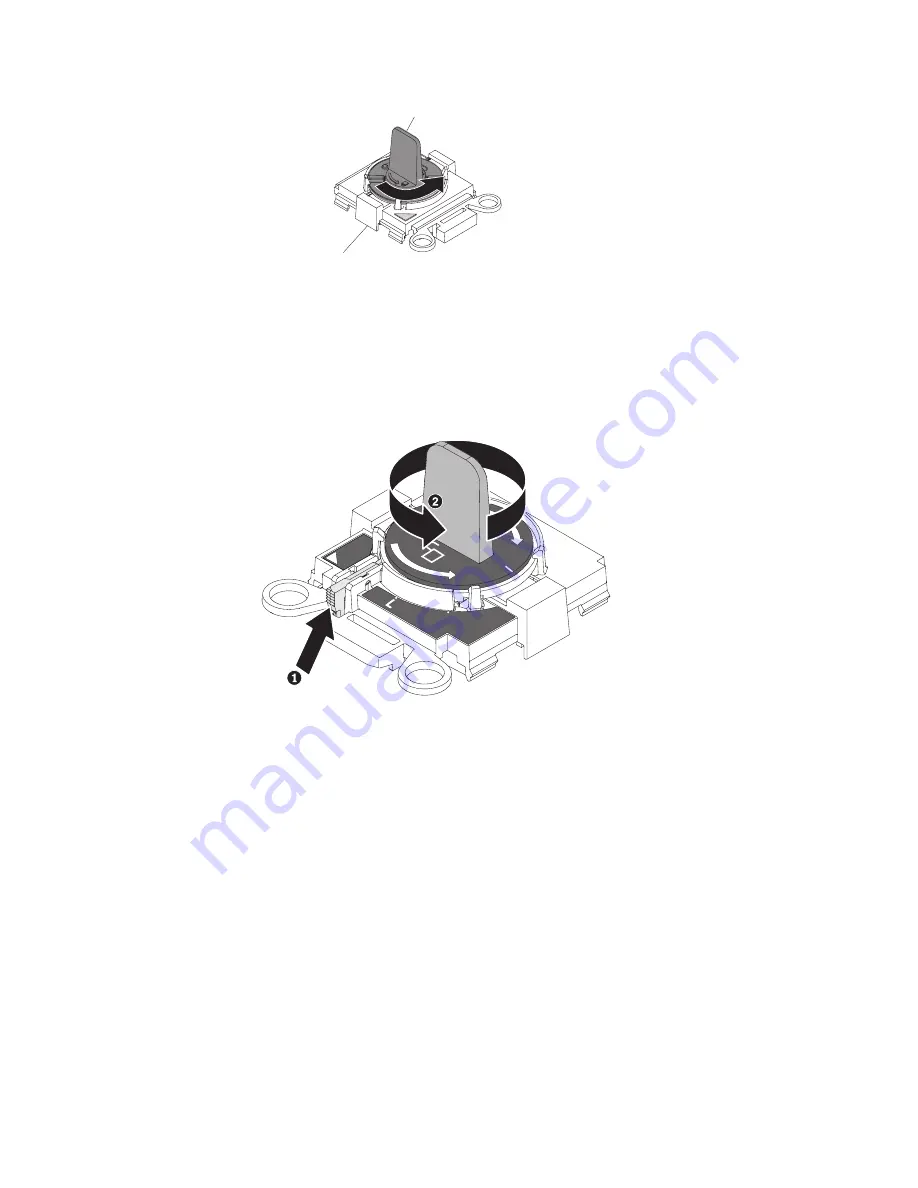
If using Installation Tool B,
1
lift the interlock latch and hold it up
while you
2
twist the microprocessor installation tool handle
counterclockwise to the open position, and then release the interlock
latch. The following illustration of the installation tool shows the
location of the interlock latch and counterclockwise rotation of the
handle before loading the microprocessor.
b.
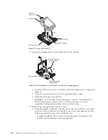
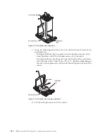
Align the installation tool with the screws, as shown in the following
graphic, and lower the installation tool on the microprocessor. The
installation tool rests flush on the socket only when it is aligned correctly.
Handle
Installation tool
Figure 216. Installation tool handle adjustment
H
Figure 217. Installation tool handle adjustment
Chapter 6. Removing and replacing components
313
Summary of Contents for Redboks System x3550 M4
Page 1: ...IBM System x3550 M4 Type 7914 Installation and Service Guide ...
Page 2: ......
Page 3: ...IBM System x3550 M4 Type 7914 Installation and Service Guide ...
Page 8: ...vi IBM System x3550 M4 Type 7914 Installation and Service Guide ...
Page 18: ...xvi IBM System x3550 M4 Type 7914 Installation and Service Guide ...
Page 42: ...24 IBM System x3550 M4 Type 7914 Installation and Service Guide ...
Page 118: ...100 IBM System x3550 M4 Type 7914 Installation and Service Guide ...
Page 214: ...196 IBM System x3550 M4 Type 7914 Installation and Service Guide ...
Page 352: ...334 IBM System x3550 M4 Type 7914 Installation and Service Guide ...
Page 702: ...684 IBM System x3550 M4 Type 7914 Installation and Service Guide ...
Page 798: ...780 IBM System x3550 M4 Type 7914 Installation and Service Guide ...
Page 802: ...784 IBM System x3550 M4 Type 7914 Installation and Service Guide ...
Page 811: ...Taiwan Class A compliance statement Notices 793 ...
Page 812: ...794 IBM System x3550 M4 Type 7914 Installation and Service Guide ...
Page 818: ...800 IBM System x3550 M4 Type 7914 Installation and Service Guide ...
Page 819: ......
Page 820: ... Part Number 00Y8006 Printed in USA 1P P N 00Y8006 ...


