Removing the system board
Use this information to remove the system board.
About this task
Notes:
1.
When you replace the system board, you must either update the server with
the latest firmware or restore the pre-existing firmware that the customer
provides on a diskette or CD image. Make sure that you have the latest
firmware or a copy of the pre-existing firmware before you proceed.
2.
When you replace the system board, make sure that you remove the Integrated
Management Module Advanced Upgrade and place it on the new system
board. For information about the Advanced Upgrade, see “Using the remote
presence and blue-screen capture features” on page 115.
3.
Before you replace the system board, make sure that you back up any features
on demand (FoD) keys that were enabled. Reactivate any Features on Demand
features. Instructions for automating the activation of features and installing
activation keys is in the
IBM Features on Demand User's Guide
. To download the
document, go to /, log in, and click
Help
.
To remove the system board, complete the following steps:
Procedure
1.
Read the safety information that begins on “Safety” on page vii, “Handling
static-sensitive devices” on page 36, and “Installation guidelines” on page 33.
2.
Turn off the server and any attached devices.
3.
Turn off the peripheral devices and disconnect all power cords.
Note:
When you replace the system board, you must either update the server
with the latest firmware or restore the pre-existing firmware that the customer
provides on a diskette or CD image. Make sure that you have the latest
firmware or a copy of the pre-existing firmware before you proceed.
4.
Pull the power supplies out of the rear of the server, just enough to disengage
them from the server.
5.
Remove the cover (see “Removing the cover” on page 36).
6.
Remove the air baffle (see “Removing the air baffle” on page 37).
7.
Remove all PCI riser-card assemblies and adapters (see “Removing a PCI
riser-card assembly” on page 244 and “Removing an adapter” on page 248).
8.
Remove the ServeRAID SAS/SATA controller (see “Removing a ServeRAID
SAS/SATA controller” on page 253).
9.
Remove the dual-port network adapter (see “Removing the dual-port network
adapter” on page 261).
10.
Remove the memory modules and set them aside on a static-protective surface
for reinstallation (see “Removing a memory module” on page 236).
Note:
Make a note of the location of each DIMM as you remove it, so that
you can later reinstall it in the same connector.
11.
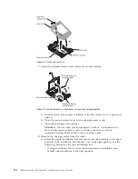
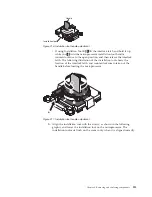
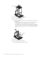
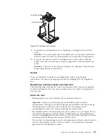
(Trained technician only) Remove all heat sinks and microprocessors, and set
them aside on a static-protective surface for reinstallation (see “Removing a
microprocessor and heat sink” on page 310).
Notes:
326
IBM System x3550 M4 Type 7914: Installation and Service Guide
Summary of Contents for Redboks System x3550 M4
Page 1: ...IBM System x3550 M4 Type 7914 Installation and Service Guide ...
Page 2: ......
Page 3: ...IBM System x3550 M4 Type 7914 Installation and Service Guide ...
Page 8: ...vi IBM System x3550 M4 Type 7914 Installation and Service Guide ...
Page 18: ...xvi IBM System x3550 M4 Type 7914 Installation and Service Guide ...
Page 42: ...24 IBM System x3550 M4 Type 7914 Installation and Service Guide ...
Page 118: ...100 IBM System x3550 M4 Type 7914 Installation and Service Guide ...
Page 214: ...196 IBM System x3550 M4 Type 7914 Installation and Service Guide ...
Page 352: ...334 IBM System x3550 M4 Type 7914 Installation and Service Guide ...
Page 702: ...684 IBM System x3550 M4 Type 7914 Installation and Service Guide ...
Page 798: ...780 IBM System x3550 M4 Type 7914 Installation and Service Guide ...
Page 802: ...784 IBM System x3550 M4 Type 7914 Installation and Service Guide ...
Page 811: ...Taiwan Class A compliance statement Notices 793 ...
Page 812: ...794 IBM System x3550 M4 Type 7914 Installation and Service Guide ...
Page 818: ...800 IBM System x3550 M4 Type 7914 Installation and Service Guide ...
Page 819: ......
Page 820: ... Part Number 00Y8006 Printed in USA 1P P N 00Y8006 ...

