v
OS Surveillance Setup Menu
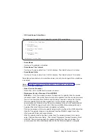
This menu can be used to set up operating system (OS) surveillance.
OS Surveillance Setup Menu
1. Surveillance:
Currently Enabled
2. Surveillance Time Interval:
5 Minutes
3. Surveillance Delay:
10 Minutes
98. Return to Previous Menu
v
Surveillance
Can be set to enabled or disabled.
v
Surveillance Time Interval
Can be set to any number from 1 to 255 minutes. The default value is 5 minutes.
v
Surveillance Delay
Can be set to any number from 0 to 255 minutes. The default value is 10 minutes.
Surveillance time interval and surveillance delay can only be changed after surveillance
is enabled.
Refer to “Service Processor System Monitoring - Surveillance” on page 179 for more
information about surveillance.
v
Reset Service Processor
Allows the user to reinitialize the service processor.
v
Reprogram Service Processor Flash EPROM
Attention:
Only the service processor firmware can be updated from the service
processor menus; the system firmware cannot be updated from the service processor
menus. A service processor firmware update always requires a companion system
firmware update which must be applied first. For this reason, updating only the
service processor firmware using the service processor menus is not recommended.
Go to the RS/6000 support web site at http://www.rs6000.ibm.com/support/micro to
download the latest firmware levels and update instructions.
The service processor firmware update image must be written onto a DOS-formatted
diskette. The update image can be obtained from the RS/6000 support web site:
http://www.rs6000.ibm.com/support/micro.
After the update diskette has been made, from the service processor main menu,
select
″
Service Processor Setup
″
. Then select
″
Reprogram Service Processor Flash
EPROM
″
. The program requests the update diskette(s) as they are needed. The
service processor will automatically reboot after the firmware update is complete.
Chapter 7. Using the Service Processor
157
Summary of Contents for RS/6000 44P Series 270
Page 1: ...RS 6000 44P Series Model 270 Service Guide SA38 0572 02 ...
Page 10: ...x Service Guide ...
Page 14: ...xiv Service Guide ...
Page 16: ...xvi Service Guide ...
Page 20: ...Rear View 1 2 3 4 5 6 7 8 9 11 12 13 14 15 16 10 17 18 19 2 Service Guide ...
Page 44: ...26 Service Guide ...
Page 164: ...146 Service Guide ...
Page 204: ...186 Service Guide ...
Page 247: ...b Slide the covers to the rear and remove Chapter 9 Removal and Replacement Procedures 229 ...
Page 288: ...270 Service Guide ...
Page 290: ...1 2 3 4 5 6 7 8 9 10 11 12 13 14 15 16 17 18 19 21 20 22 23 24 25 272 Service Guide ...
Page 294: ...Keyboards and Mouse 276 Service Guide ...
Page 296: ...Keyboards and Mouse Black 278 Service Guide ...
Page 298: ...Power Cables 1 2 3 4 5 6 7 8 9 10 11 280 Service Guide ...
Page 300: ...282 Service Guide ...
Page 302: ...284 Service Guide ...
Page 304: ...286 Service Guide ...
Page 310: ...292 Service Guide ...
Page 338: ...320 Service Guide ...
Page 345: ......
Page 346: ... Printed in U S A September 2001 SA38 0572 02 ...


