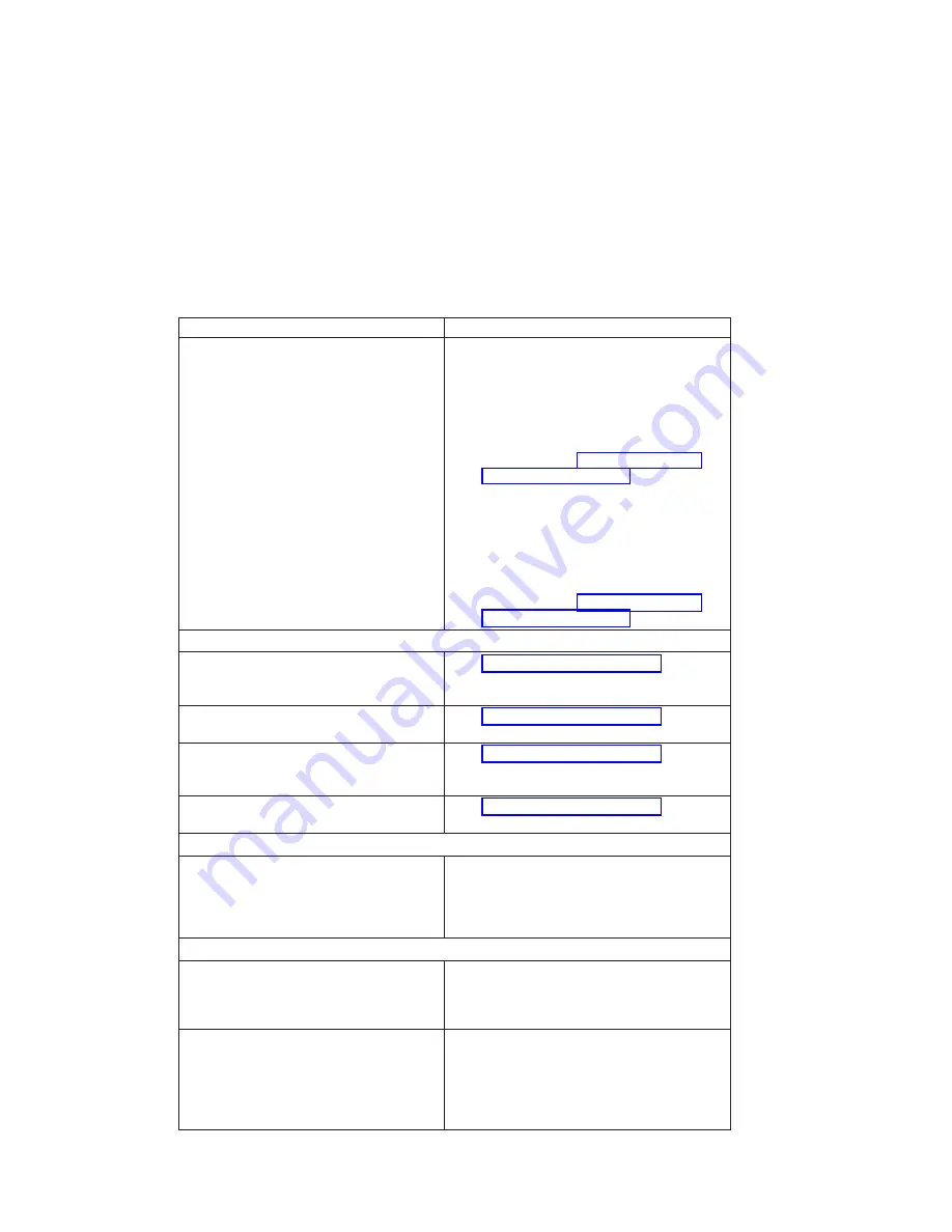
Symptom
Action
All display problems.
v
If using a graphics display:
1. Go to the
problem determination
procedures
for the display.
2. If you do not find a problem, replace the
display adapter.
3. If you do not find a problem, suspect the
I/O board. Go to “MAP 1540: Minimum
Configuration” on page 50.
v
Using an ASCII terminal:
1. Make sure that the ASCII terminal is
connected to S1.
2. If problems persist, go to the
problem
determination procedures
for the terminal.
3. If you do not find a problem, suspect the
I/O board. Go to “MAP 1540: Minimum
Configuration” on page 50.
Power and Cooling Problems
The power LEDs on the operator panel and
the power supply do not start flashing within
30 seconds of ac power application.
Go to “MAP 1520: Power” on page 45.
The power LEDs on the operator panel and
the power supply do not come on or stay on.
Go to “MAP 1520: Power” on page 45.
The power LEDs on the operator panel and
the power supply come on and stay on but
the system does not power on.
Go to “MAP 1520: Power” on page 45.
The cooling fan(s) do not come on or come
on but do not stay on.
Go to “MAP 1520: Power” on page 45.
Flashing 888 in Operator Panel Display
888 is displayed in the operator panel.
Go to the Fast Path MAP in the
RS/6000 and
Eserver
pSeries Diagnostics Information for
Multiple Bus Systems
.
Other Symptoms or Problems
You have OK displayed.
The service processor is ready. Go to
″
MAP
0020: Problem Determination Procedure
″
in the
RS/6000 and
Eserver
pSeries Diagnostics
Information for Multiple Bus Systems
.
You have STBY displayed.
The service processor is ready. The system was
shut down by the operating system and is still
powered on. This condition can be requested by
a privileged system user with no faults. See
service processor error log for possible operating
system fault indications.
30
Service Guide
Summary of Contents for RS/6000 44P Series 270
Page 1: ...RS 6000 44P Series Model 270 Service Guide SA38 0572 02 ...
Page 10: ...x Service Guide ...
Page 14: ...xiv Service Guide ...
Page 16: ...xvi Service Guide ...
Page 20: ...Rear View 1 2 3 4 5 6 7 8 9 11 12 13 14 15 16 10 17 18 19 2 Service Guide ...
Page 44: ...26 Service Guide ...
Page 164: ...146 Service Guide ...
Page 204: ...186 Service Guide ...
Page 247: ...b Slide the covers to the rear and remove Chapter 9 Removal and Replacement Procedures 229 ...
Page 288: ...270 Service Guide ...
Page 290: ...1 2 3 4 5 6 7 8 9 10 11 12 13 14 15 16 17 18 19 21 20 22 23 24 25 272 Service Guide ...
Page 294: ...Keyboards and Mouse 276 Service Guide ...
Page 296: ...Keyboards and Mouse Black 278 Service Guide ...
Page 298: ...Power Cables 1 2 3 4 5 6 7 8 9 10 11 280 Service Guide ...
Page 300: ...282 Service Guide ...
Page 302: ...284 Service Guide ...
Page 304: ...286 Service Guide ...
Page 310: ...292 Service Guide ...
Page 338: ...320 Service Guide ...
Page 345: ......
Page 346: ... Printed in U S A September 2001 SA38 0572 02 ...


