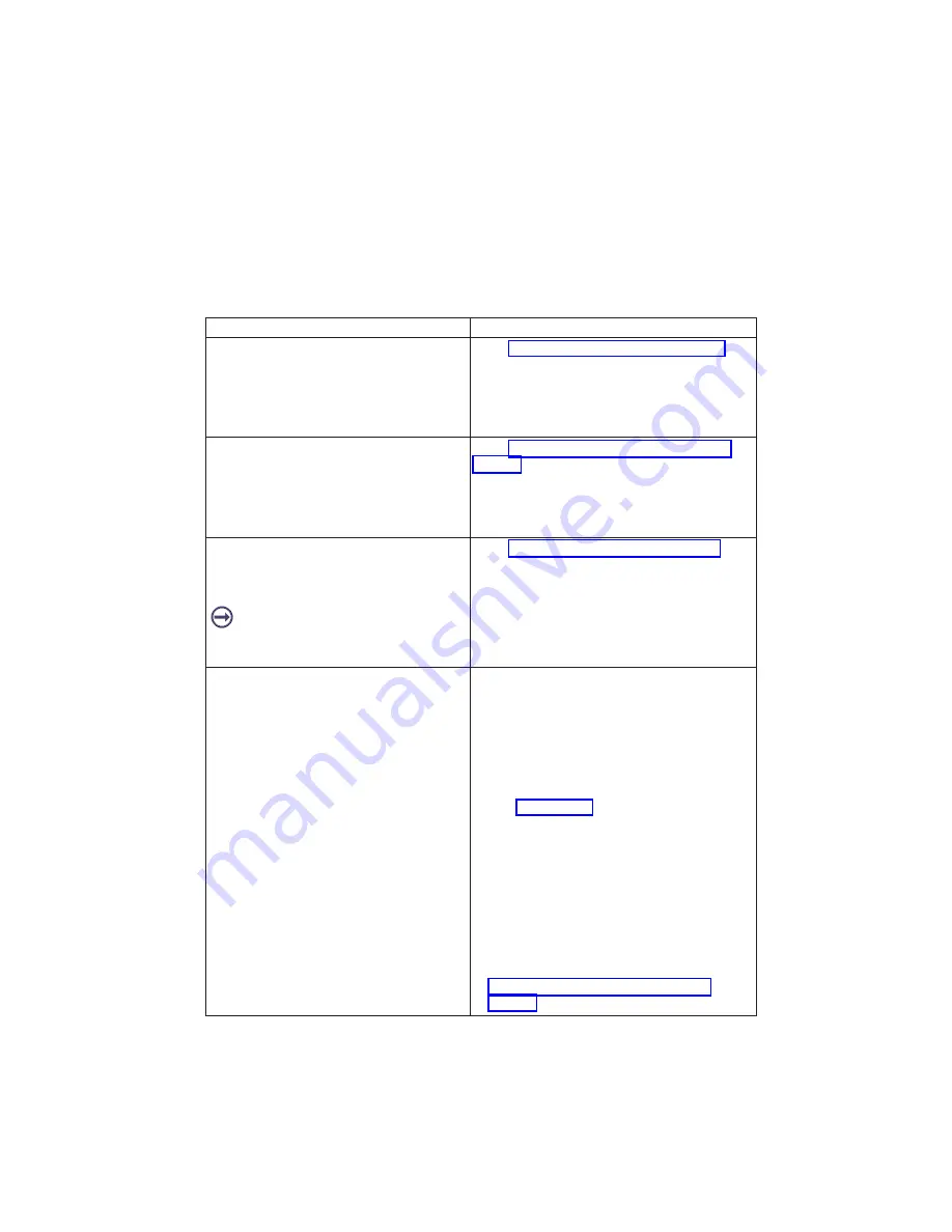
Symptom
Action
The system POST indicators are displayed on
the system console; the system pauses and
then restarts. The term
″
POST indicators
″
refers to the icons (graphic display) or device
mnemonics (ASCII terminal) that appear
during the power-on self-test (POST).
Go to “Boot Problems/Concerns” on page 90.
The system stops and POST indicators are
displayed on the system console. The term
″
POST indicators
″
refers to the icons (graphic
display) or device mnemonics (ASCII
terminal) that appear during the power-on
self-test (POST).
Go to “MAP 1540: Minimum Configuration” on
page 50 to isolate the problem.
The system stops and the message
″
STARTING SOFTWARE PLEASE WAIT...
″
is
displayed on the ASCII terminal, or the boot
indicator
is displayed on a graphics terminal.
Go to Chapter 4, “Checkpoints”, on page 71.
The system does not respond to the
password being entered, or the system login
prompt is displayed when booting in service
mode.
Verify that the password is being entered from
the ASCII terminal or keyboard defined as the
system console. If so, then the keyboard or its
controller may be faulty.
v
If entering the password from the keyboard
which is attached to the system, replace the
keyboard. If replacing the keyboard does not
fix the problem, replace the I/O board. (See
note 4 on page 27.)
v
If entering the password from a keyboard
which is attached to an ASCII terminal, use the
problem determination procedures for the
ASCII terminal. Make sure the ASCII terminal
is connected to S1. Replace the I/O board if
these procedures do not reveal a problem.
v
If the problem is fixed, go to "MAP 410: Repair
Checkout" in the
RS/6000 and
Eserver
pSeries Diagnostics Information for Multiple
Bus Systems
. If the problem persists, go to
“MAP 1540: Minimum Configuration” on
page 50 to isolate the problem.
Chapter 3. Maintenance Analysis Procedures
31
Summary of Contents for RS/6000 44P Series 270
Page 1: ...RS 6000 44P Series Model 270 Service Guide SA38 0572 02 ...
Page 10: ...x Service Guide ...
Page 14: ...xiv Service Guide ...
Page 16: ...xvi Service Guide ...
Page 20: ...Rear View 1 2 3 4 5 6 7 8 9 11 12 13 14 15 16 10 17 18 19 2 Service Guide ...
Page 44: ...26 Service Guide ...
Page 164: ...146 Service Guide ...
Page 204: ...186 Service Guide ...
Page 247: ...b Slide the covers to the rear and remove Chapter 9 Removal and Replacement Procedures 229 ...
Page 288: ...270 Service Guide ...
Page 290: ...1 2 3 4 5 6 7 8 9 10 11 12 13 14 15 16 17 18 19 21 20 22 23 24 25 272 Service Guide ...
Page 294: ...Keyboards and Mouse 276 Service Guide ...
Page 296: ...Keyboards and Mouse Black 278 Service Guide ...
Page 298: ...Power Cables 1 2 3 4 5 6 7 8 9 10 11 280 Service Guide ...
Page 300: ...282 Service Guide ...
Page 302: ...284 Service Guide ...
Page 304: ...286 Service Guide ...
Page 310: ...292 Service Guide ...
Page 338: ...320 Service Guide ...
Page 345: ......
Page 346: ... Printed in U S A September 2001 SA38 0572 02 ...


