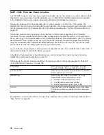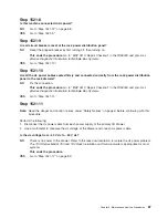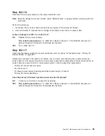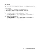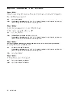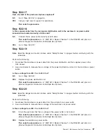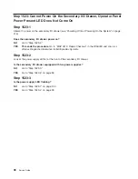
MAP
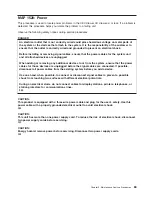
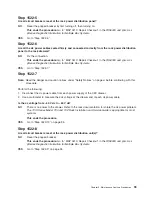
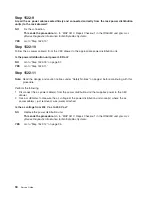
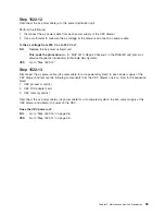
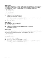
1520:
Power
This
procedure
is
used
to
locate
power
problems
in
the
CEC
drawer,
I/O
drawer(s)
or
rack.
If
a
problem
is
detected,
this
procedure
helps
you
isolate
the
problem
to
a
failing
unit.
Observe
the
following
safety
notices
during
service
procedures.
DANGER
An
electrical
outlet
that
is
not
correctly
wired
could
place
hazardous
voltage
on
metal
parts
of
the
system
or
the
devices
that
attach
to
the
system.
It
is
the
responsibility
of
the
customer
to
ensure
that
the
outlet
is
correctly
wired
and
grounded
to
prevent
an
electrical
shock.
Before
installing
or
removing
signal
cables,
ensure
that
the
power
cables
for
the
system
unit
and
all
attached
devices
are
unplugged.
When
adding
or
removing
any
additional
devices
to
or
from
the
system,
ensure
that
the
power
cables
for
those
devices
are
unplugged
before
the
signal
cables
are
connected.
If
possible,
disconnect
all
power
cables
from
the
existing
system
before
you
add
a
device.
Use
one
hand,
when
possible,
to
connect
or
disconnect
signal
cables
to
prevent
a
possible
shock
from
touching
two
surfaces
with
different
electrical
potentials.
During
an
electrical
storm,
do
not
connect
cables
for
display
stations,
printers,
telephones,
or
station
protectors
for
communications
lines.
D05
CAUTION:
This
product
is
equipped
with
a
three-wire
power
cable
and
plug
for
the
user’s
safety.
Use
this
power
cable
with
a
properly
grounded
electrical
outlet
to
avoid
electrical
shock.
C01
CAUTION:
This
unit
has
more
than
one
power
supply
cord.
To
reduce
the
risk
of
electrical
shock,
disconnect
two
power
supply
cords
before
servicing.
C21
CAUTION:
Energy
hazard,
remove
power
before
servicing.
Disconnect
two
power
supply
cords.
C23
Chapter
3.
Maintenance
Analysis
Procedures
83
Summary of Contents for RS/6000 Enterprise Server M80
Page 1: ...RS 6000 Enterprise Server Model M80 Eserver pSeries 660 Model 6M1 Service Guide SA38 0571 01...
Page 10: ...x Service Guide...
Page 14: ...xiv Service Guide...
Page 16: ...xvi Service Guide...
Page 22: ...Data Flow 4 Service Guide...
Page 30: ...CEC Card Cage Rear of CEC drawer viewed from top cover removed 12 Service Guide...
Page 84: ...66 Service Guide...
Page 176: ...158 Service Guide...
Page 376: ...358 Service Guide...
Page 430: ...412 Service Guide...
Page 485: ...Chapter 11 Parts Information This chapter contains parts information for the system 467...
Page 486: ...CEC Drawer Card Assembly 9 468 Service Guide...
Page 488: ...CEC Drawer Backplane 5 2a 1 2 3 4 470 Service Guide...
Page 490: ...CEC Drawer Power Supplies 1 2 3 4 5 6 7 8 9 472 Service Guide...
Page 492: ...CEC Drawer Fan Assemblies 2 1 3 4 5 6 8 9 10 11 12 13 7 14 474 Service Guide...
Page 496: ...7 8 9 10 6 1 2 3 4 4 5 478 Service Guide...
Page 508: ...490 Service Guide...
Page 520: ...502 Service Guide...
Page 522: ...504 Service Guide...
Page 526: ...508 Service Guide...
Page 558: ...540 Service Guide...
Page 565: ......

