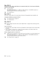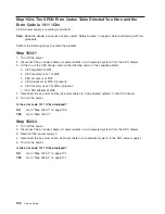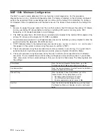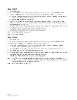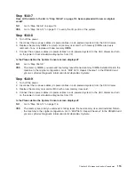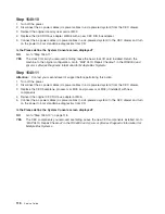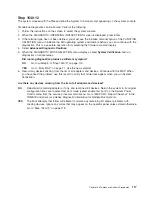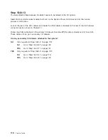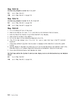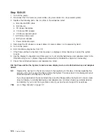
Step
1540-10
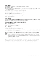
1.
Turn
off
the
power.
2.
Disconnect
the
ac
power
cables
(dc
power
cables
in
a
dc-powered
system)
from
the
CEC
drawer.
3.
Reinsert
the
original
memory
riser
card
at
M02.
4.
Replace
the
CEC
RIO
bus
adapter
at
M06
with
a
new
CEC
RIO
bus
adapter.
5.
Connect
the
ac
power
cables
(dc
power
cables
in
a
dc-powered
system)
to
the
CEC
drawer
and
turn
on
the
power
to
boot
standalone
diagnostics
from
CD.
Is
the
Please
define
the
System
Console
screen
displayed?
NO
Go
to
“Step
1540-11.”
YES
The
clock
I/O
card
you
removed
is
failing;
leave
the
new
clock
I/O
card
installed.
Return
the
machine
to
the
original
configuration.
Go
to
″
MAP
0410:
Repair
Checkout
″
in
the
RS/6000
and
Eserver
pSeries
Diagnostic
Information
for
Multiple
Bus
Systems
.
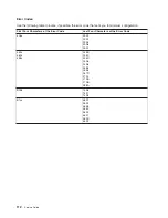
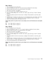
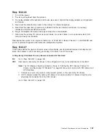
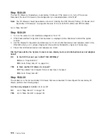
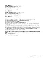
Step
1540-11
Attention:
Contact
your
second
level
of
support
before
performing
this
action.
1.
Turn
off
the
power.
2.
Disconnect
the
ac
power
cables
(dc
power
cables
in
a
dc-powered
system)
from
the
CEC
drawer.
3.
Replace
the
CEC
backplane,
processor
at
M03,
and
processor
at
M04
(if
installed)
with
new
components.
4.
Reinsert
the
original
CEC
RIO
bus
adapter
at
M06.
5.
Connect
the
ac
power
cables
(dc
power
cables
in
a
dc-powered
system)
to
the
CEC
drawer
and
turn
on
the
power
to
boot
standalone
diagnostics
from
CD.
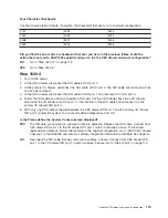
Is
the
Please
define
the
System
Console
screen
displayed?
NO
Go
to
“Step
1540-13”
on
page
118.
YES
The
CEC
components
you
removed
are
failing.
Leave
the
new
CEC
components
installed.
Go
to
″
MAP
0410:
Repair
Checkout
″
in
the
RS/6000
and
Eserver
pSeries
Diagnostic
Information
for
Multiple
Bus
Systems
.
116
Service
Guide
Summary of Contents for RS/6000 Enterprise Server M80
Page 1: ...RS 6000 Enterprise Server Model M80 Eserver pSeries 660 Model 6M1 Service Guide SA38 0571 01...
Page 10: ...x Service Guide...
Page 14: ...xiv Service Guide...
Page 16: ...xvi Service Guide...
Page 22: ...Data Flow 4 Service Guide...
Page 30: ...CEC Card Cage Rear of CEC drawer viewed from top cover removed 12 Service Guide...
Page 84: ...66 Service Guide...
Page 176: ...158 Service Guide...
Page 376: ...358 Service Guide...
Page 430: ...412 Service Guide...
Page 485: ...Chapter 11 Parts Information This chapter contains parts information for the system 467...
Page 486: ...CEC Drawer Card Assembly 9 468 Service Guide...
Page 488: ...CEC Drawer Backplane 5 2a 1 2 3 4 470 Service Guide...
Page 490: ...CEC Drawer Power Supplies 1 2 3 4 5 6 7 8 9 472 Service Guide...
Page 492: ...CEC Drawer Fan Assemblies 2 1 3 4 5 6 8 9 10 11 12 13 7 14 474 Service Guide...
Page 496: ...7 8 9 10 6 1 2 3 4 4 5 478 Service Guide...
Page 508: ...490 Service Guide...
Page 520: ...502 Service Guide...
Page 522: ...504 Service Guide...
Page 526: ...508 Service Guide...
Page 558: ...540 Service Guide...
Page 565: ......

