
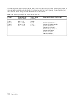
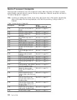
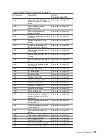

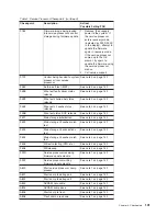
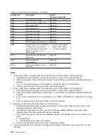

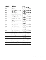
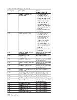
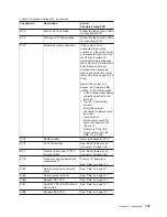


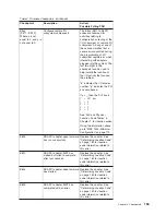


Table
2.
Firmware
Checkpoints
(continued)
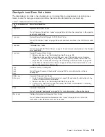
Checkpoint
Description
Action/
Possible
Failing
FRU
E150
Create
host
(primary)
PCI
controller
node
1.
If
a
location
code
is
associated
with
the
checkpoint,
replace
the
adapter
identified
by
the
location
code.
See
“Determining
Location
Code”
on
page
160.
If
a
network
adapter
is
replaced,
see
“Replacing
the
Network
Adapter”
on
page
159.
2.
Replace
the
drawer
I/O
backplane.
E151
Probing
primary
PCI
bus
1.
If
a
location
code
is
associated
with
the
checkpoint,
replace
the
FRU
identified
by
the
location
code.
See
“Determining
Location
Code”
on
page
160.
If
a
network
adapter
is
replaced,
see
“Replacing
the
Network
Adapter”
on
page
159.
2.
Replace
the
drawer
I/O
backplane.
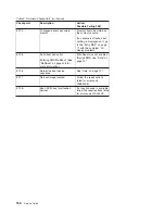
E152
Probing
for
adapter
FCODE,
evaluate
if
present
Follow
the
repair
action
listed
for
checkpoint
E151.
E153
End
adapter
FCODE,
probe/evaluate
See
“Note”
on
page
137.
E154
Create
PCI
bridge
node
Follow
the
repair
action
listed
for
checkpoint
E151.
E155
Probing
PCI
bridge
secondary
bus
Follow
the
repair
action
listed
for
checkpoint
E151.
E156
Create
PCI
ethernet
node
Follow
the
repair
action
listed
for
checkpoint
E151.
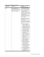
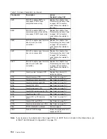
E15A
Create
64-bit
host
(primary)
PCI
controller
node
See
“Note”
on
page
144.
E15B
Transferring
control
to
operating
system
(service
mode
boot)
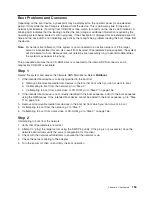
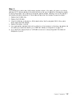
See
“Boot
Problems
and
Concerns”
on
page
155.
E15C
Probe
primary
64-bit
PCI
bus
See
“Note”
on
page
144.
E15D
Create
host
PCI
controller
node
See
“Note”
on
page
144.
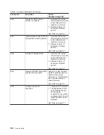
E15F
Adapter
VPD
probe
Follow
the
repair
action
listed
for
checkpoint
E151.
E162
SP
node
VPD
creation
See
“Note”
on
page
144.
E163
Create
CPU
VPD
See
“Note”
on
page
144.
E165
Create
planar-clock
VPD
See
“Note”
on
page
144.
E166
Create
CEC
VPD
See
“Note”
on
page
144.
E167
Collect
power
cards
VPD.
See
“Note”
on
page
144.
146
Service
Guide
Summary of Contents for RS/6000 Enterprise Server M80
Page 1: ...RS 6000 Enterprise Server Model M80 Eserver pSeries 660 Model 6M1 Service Guide SA38 0571 01...
Page 10: ...x Service Guide...
Page 14: ...xiv Service Guide...
Page 16: ...xvi Service Guide...
Page 22: ...Data Flow 4 Service Guide...
Page 30: ...CEC Card Cage Rear of CEC drawer viewed from top cover removed 12 Service Guide...
Page 84: ...66 Service Guide...
Page 176: ...158 Service Guide...
Page 376: ...358 Service Guide...
Page 430: ...412 Service Guide...
Page 485: ...Chapter 11 Parts Information This chapter contains parts information for the system 467...
Page 486: ...CEC Drawer Card Assembly 9 468 Service Guide...
Page 488: ...CEC Drawer Backplane 5 2a 1 2 3 4 470 Service Guide...
Page 490: ...CEC Drawer Power Supplies 1 2 3 4 5 6 7 8 9 472 Service Guide...
Page 492: ...CEC Drawer Fan Assemblies 2 1 3 4 5 6 8 9 10 11 12 13 7 14 474 Service Guide...
Page 496: ...7 8 9 10 6 1 2 3 4 4 5 478 Service Guide...
Page 508: ...490 Service Guide...
Page 520: ...502 Service Guide...
Page 522: ...504 Service Guide...
Page 526: ...508 Service Guide...
Page 558: ...540 Service Guide...
Page 565: ......


