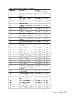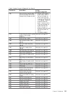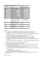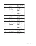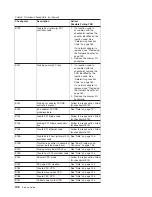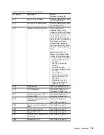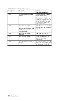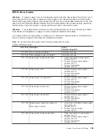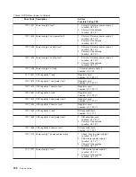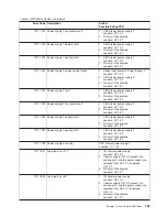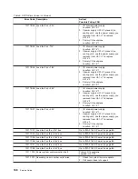
Table
2.
Firmware
Checkpoints
(continued)
Checkpoint
Description
Action/
Possible
Failing
FRU
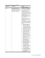
E5xy
(E511
-
E5FF)
Where
x
is
not
equal
to
0,
and
y
is
not
equal
to
0.
Configure
remote
I/O
subsystem
components
The
E5xy
(E511
to
E5FF)
codes
are
reserved
for
activities
relating
to
configuration
or
testing
of
the
I/O
subsystem,
or
remote
I/O
subsystem.
A
hang
at
one
of
these
codes
implies
that
a
severe
error
occurred
during
the
programming
of
I/O
subsystem
registers
or
when
interacting
with
adapters
plugged
into
the
system.
The
last
two
digits
in
the
checkpoint
can
be
used
to
help
isolate
the
location
of
the
I/O
activity
that
caused
the
problem.
“
x
”
indicates
the
I/O
drawer
number.
“
y
”
indicates
the
PCI
bus
occurrence.
If
y
=_,
then
the
PCI
bus
is:
Y
=
PCI
bus
1
=
0
2
=
1
3
=
2
4
=
3
See
“AIX
and
Physical
Location
Code
Tables”
in
Chapter
1,
for
location
codes.
Using
the
information
above,
go
to
“MAP
1540:
Minimum
Configuration”
on
page
110.
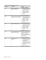
E600
SSA
PCI
adapter
open
firmware
has
run
successfully.
Replace
the
adapter.
See
“Determining
Location
Code”
on
page
160
for
location
code
information
related
to
this
error.
E601
SSA
PCI
adapter
BIST
has
started
but
failed
to
complete
after
four
seconds.
Replace
the
adapter.
See
“Determining
Location
Code”
on
page
160
for
location
code
information
related
to
this
error.
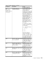
E602
SSA
PCI
adapter
open
firmware
has
started.
Replace
the
adapter.
See
“Determining
Location
Code”
on
page
160
for
location
code
information
related
to
this
error.
E603
SSA
PCI
adapter
BIST
has
completed
with
an
error.
Replace
the
adapter.
See
“Determining
Location
Code”
on
page
160
for
location
code
information
related
to
this
error.
Chapter
4.
Checkpoints
153
Summary of Contents for RS/6000 Enterprise Server M80
Page 1: ...RS 6000 Enterprise Server Model M80 Eserver pSeries 660 Model 6M1 Service Guide SA38 0571 01...
Page 10: ...x Service Guide...
Page 14: ...xiv Service Guide...
Page 16: ...xvi Service Guide...
Page 22: ...Data Flow 4 Service Guide...
Page 30: ...CEC Card Cage Rear of CEC drawer viewed from top cover removed 12 Service Guide...
Page 84: ...66 Service Guide...
Page 176: ...158 Service Guide...
Page 376: ...358 Service Guide...
Page 430: ...412 Service Guide...
Page 485: ...Chapter 11 Parts Information This chapter contains parts information for the system 467...
Page 486: ...CEC Drawer Card Assembly 9 468 Service Guide...
Page 488: ...CEC Drawer Backplane 5 2a 1 2 3 4 470 Service Guide...
Page 490: ...CEC Drawer Power Supplies 1 2 3 4 5 6 7 8 9 472 Service Guide...
Page 492: ...CEC Drawer Fan Assemblies 2 1 3 4 5 6 8 9 10 11 12 13 7 14 474 Service Guide...
Page 496: ...7 8 9 10 6 1 2 3 4 4 5 478 Service Guide...
Page 508: ...490 Service Guide...
Page 520: ...502 Service Guide...
Page 522: ...504 Service Guide...
Page 526: ...508 Service Guide...
Page 558: ...540 Service Guide...
Page 565: ......

