


v
A
processor
or
memory
DIMM
reaches
a
threshold
of
recovered
failures
that
results
in
a
predictive
callout
(as
determined
by
the
processor
run-time
diagnostics
in
the
service
processor).
During
boot
time,
the
service
processor
does
not
configure
processors
or
memory
DIMMs
that
are
marked
″
bad.
″
If
a
processor
or
memory
DIMM
is
deconfigured,
the
processor
or
memory
DIMM
remains
offline
for
subsequent
reboots
until
it
is
replaced
or
Repeat
Gard
is
disabled.
The
Repeat
Gard
function
also
allows
users
to
manually
deconfigure
a
processor
or
memory
DIMM,
or
re-enable
a
previously
deconfigured
processor
or
memory
DIMM.
For
information
on
configuring
or
deconfiguring
a
processor,
see
the
Processor
Configuration/Deconfiguration
Menu
on
page
373.
For
information
on
configuring
or
deconfiguring
a
memory
DIMM,
see
the
Memory
Configuration/Deconfiguration
Menu
on
page
374.
Both
of
these
are
submenus
under
the
System
Information
Menu.
You
can
enable
or
disable
CPU
Repeat
Gard
or
Memory
Repeat
Gard
using
the
Processor
Configuration/Deconfiguration
Menu,
which
is
a
submenu
under
the
System
Information
Menu.
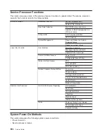
Run-Time
CPU
Deconfiguration
(CPU
Gard)
L1
instruction
cache
recoverable
errors,
L1
data
cache
correctable
errors,
and
L2
cache
correctable
errors
are
monitored
by
the
processor
run
time
diagnostics
(PRD)
code
running
in
the
service
processor.
When
a
predefined
error
threshold
is
met,
an
error
log
entry
with
warning
severity
and
threshold
exceeded
status
is
returned
to
AIX.
At
the
same
time,
PRD
marks
the
CPU
for
deconfiguration
at
the
next
boot.
AIX
will
attempt
to
migrate
all
resources
associated
with
that
processor
to
another
processor
and
then
stop
the
defective
processor.
Service
Processor
System
Monitoring
-
Surveillance
Surveillance
is
a
function
in
which
the
service
processor
monitors
the
system,
and
the
system
monitors
the
service
processor.
This
monitoring
is
accomplished
by
periodic
samplings
called
heartbeats
.
Surveillance
is
available
during
two
phases:
v
System
firmware
bring-up
(automatic)
v
Operating
system
run
time
(optional)
System
Firmware
Surveillance
System
firmware
surveillance
is
automatically
enabled
during
system
power-on.
It
cannot
be
disabled
by
the
user,
and
the
surveillance
interval
and
surveillance
delay
cannot
be
changed
by
the
user.
If
the
service
processor
detects
no
heartbeats
during
system
IPL
(for
a
set
time
period),
it
cycles
the
system
power
to
attempt
a
reboot.
The
maximum
number
of
retries
is
set
from
the
service
processor
menus.
If
the
fail
condition
persists,
the
service
processor
leaves
the
machine
powered
on,
logs
an
error,
and
displays
menus
to
the
user.
If
call-out
is
enabled,
the
service
processor
calls
to
report
the
failure
and
displays
the
operating
system
surveillance
failure
code
on
the
operator
panel.
Operating
System
Surveillance
Operating
system
surveillance
provides
the
service
processor
with
a
means
to
detect
hang
conditions,
as
well
as
hardware
or
software
failures,
while
the
operating
system
is
running.
It
also
provides
the
operating
system
with
a
means
to
detect
a
service
processor
failure
caused
by
the
lack
of
a
return
heartbeat.
Operating
system
surveillance
is
not
enabled
by
default,
allowing
you
to
run
operating
systems
that
do
not
support
this
service
processor
option.
You
can
also
use
the
service
processor
menus
and
the
AIX
diagnostic
service
aids
to
enable
or
disable
operating
system
surveillance.
Chapter
8.
Using
the
Service
Processor
393
Summary of Contents for RS/6000 Enterprise Server M80
Page 1: ...RS 6000 Enterprise Server Model M80 Eserver pSeries 660 Model 6M1 Service Guide SA38 0571 01...
Page 10: ...x Service Guide...
Page 14: ...xiv Service Guide...
Page 16: ...xvi Service Guide...
Page 22: ...Data Flow 4 Service Guide...
Page 30: ...CEC Card Cage Rear of CEC drawer viewed from top cover removed 12 Service Guide...
Page 84: ...66 Service Guide...
Page 176: ...158 Service Guide...
Page 376: ...358 Service Guide...
Page 430: ...412 Service Guide...
Page 485: ...Chapter 11 Parts Information This chapter contains parts information for the system 467...
Page 486: ...CEC Drawer Card Assembly 9 468 Service Guide...
Page 488: ...CEC Drawer Backplane 5 2a 1 2 3 4 470 Service Guide...
Page 490: ...CEC Drawer Power Supplies 1 2 3 4 5 6 7 8 9 472 Service Guide...
Page 492: ...CEC Drawer Fan Assemblies 2 1 3 4 5 6 8 9 10 11 12 13 7 14 474 Service Guide...
Page 496: ...7 8 9 10 6 1 2 3 4 4 5 478 Service Guide...
Page 508: ...490 Service Guide...
Page 520: ...502 Service Guide...
Page 522: ...504 Service Guide...
Page 526: ...508 Service Guide...
Page 558: ...540 Service Guide...
Page 565: ......