


Service
Processor
Operational
Phases
This
section
provides
a
high-level
flow
of
the
phases
of
the
service
processor.
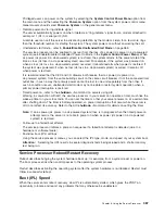
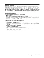
SP Power Applied
Pre-Standby Phase
Standby Phase SP Menus Available
Bring-Up Phase SMS Menus Available
Run-time Phase Operating System Login Prompt Available
Pre-Standby
Phase
This
phase
is
entered
when
the
server
is
first
connected
to
a
power
source.
This
phase
is
exited
when
the
power-on
self-test
(POST)
and
configuration
tasks
are
completed.
The
pre-standby
phase
components
are:
v
Service
processor
initialization
-
the
service
processor
performs
any
necessary
hardware
and
firmware
initializations.
v
Service
processor
POST
-
the
service
processor
conducts
power-on
self-tests
on
its
work
and
code
areas.
v
Service
processor
unattended
start
mode
checks
-
To
assist
fault
recovery.
If
unattended
start
mode
is
set,
the
service
processor
automatically
reboots
the
server.
The
service
processor
does
not
wait
for
user
input
or
a
power-on
command,
but
moves
through
the
phase
and
into
the
bring-up
phase.
Access
the
system
management
services
(SMS)
menus
or
the
service
processor
menus
to
reset
the
unattended
start
mode.
Standby
Phase
The
standby
phase
can
be
reached
in
either
of
the
following
ways:
v
With
the
server
off
and
power
connected
(the
normal
path),
recognized
by
OK
in
the
LCD
display.
OR
v
With
the
server
on
after
an
operating
system
fault,
recognized
by
an
8-digit
code
in
the
LCD
display.
In
the
standby
phase,
the
service
processor
takes
care
of
some
automatic
duties
and
its
menus
are
available.
The
service
processor
remains
in
the
standby
phase
until
a
power-on
request
is
detected.
398
Service
Guide
Summary of Contents for RS/6000 Enterprise Server M80
Page 1: ...RS 6000 Enterprise Server Model M80 Eserver pSeries 660 Model 6M1 Service Guide SA38 0571 01...
Page 10: ...x Service Guide...
Page 14: ...xiv Service Guide...
Page 16: ...xvi Service Guide...
Page 22: ...Data Flow 4 Service Guide...
Page 30: ...CEC Card Cage Rear of CEC drawer viewed from top cover removed 12 Service Guide...
Page 84: ...66 Service Guide...
Page 176: ...158 Service Guide...
Page 376: ...358 Service Guide...
Page 430: ...412 Service Guide...
Page 485: ...Chapter 11 Parts Information This chapter contains parts information for the system 467...
Page 486: ...CEC Drawer Card Assembly 9 468 Service Guide...
Page 488: ...CEC Drawer Backplane 5 2a 1 2 3 4 470 Service Guide...
Page 490: ...CEC Drawer Power Supplies 1 2 3 4 5 6 7 8 9 472 Service Guide...
Page 492: ...CEC Drawer Fan Assemblies 2 1 3 4 5 6 8 9 10 11 12 13 7 14 474 Service Guide...
Page 496: ...7 8 9 10 6 1 2 3 4 4 5 478 Service Guide...
Page 508: ...490 Service Guide...
Page 520: ...502 Service Guide...
Page 522: ...504 Service Guide...
Page 526: ...508 Service Guide...
Page 558: ...540 Service Guide...
Page 565: ......


