v
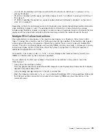
U0.1-P1/Z1–A3
identifies
a
SCSI
device
with
SCSI
ID
3
attached
to
SCSI
bus
1
on
planar
1
in
the
primary
I/O
drawer.
v
P2-Z1-A3.1
identifies
a
SCSI
device
with
SCSI
address
of
LUN
1
at
SCSI
ID
3
attached
to
SCSI
bus
1
from
planar
2.
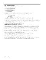
v
P1-I2#E3.2
identifies
the
second
in
a
series
of
cables
attached
to
Ethernet
controller
3
on
the
card
in
slot
2
(I2)
on
planar
P1.
Depending
on
the
AIX
and
firmware
levels,
AIX
Diagnostics
may
include
the
extended
location
information
when
identifying
a
planar
or
card.
The
extended
location
information
or
cable
information
is
always
included
when
identifying
a
cable
or
connector.
Location
codes
with
extended
location
information
that
are
displayed
without
a
description
identifying
the
devices
always
identify
the
cable
attached
to
the
port.
Multiple
FRU
Callout
Instructions
If
an
eight-digit
error
code
appears
in
the
operator
panel
display
or
in
Chapter
5,
“Error
Code
to
FRU
Index,”
on
page
159,
a
location
code
for
a
failing
part
may
also
be
specified.
If
the
location
code
includes
a
blank
space
followed
by
a
lowercase
x
followed
by
a
number,
this
is
an
error
code
with
multiple
FRU
callouts.
This
error
can
typically
happen
with
memory
DIMMs,
memory
riser
cards,
or
processors
and
may
involve
mixed
types
of
parts.
In
this
case,
check
the
system’s
configuration
for
FRU
part
numbers
to
determine
the
appropriate
set
of
FRUs.
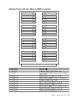
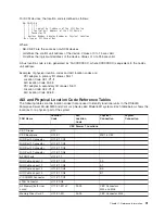
For
example,
if
the
location
code
U1.1-P1-M1.1
x4
was
displayed,
this
indicates
memory
quad
A
(four
DIMMs)
on
the
first
memory
riser
card
was
suspected.
You
can
determine
the
FRU
part
numbers
of
the
electronic
assemblies
in
the
system
in
one
of
the
following
ways:
v
Using
the
service
processor
menus
From
the
general
user
menu,
select
Read
VPD
Image
from
Last
System
Boot,
then
enter
90
to
display
detailed
vital
product
data
(VPD).
v
Using
the
lscfg
-vp
|
pg
command
on
the
AIX
command
line
Enter
the
following
command:
lscfg
-vp
|
pg
to
display
the
detailed
VPD
of
all
assemblies.
Notice
that
the
FRU
part
number
information
for
processors
and
memory
DIMMs
may
be
at
the
bottom
of
the
command
output.
Chapter
1.
Reference
Information
29
Summary of Contents for RS/6000 Enterprise Server M80
Page 1: ...RS 6000 Enterprise Server Model M80 Eserver pSeries 660 Model 6M1 Service Guide SA38 0571 01...
Page 10: ...x Service Guide...
Page 14: ...xiv Service Guide...
Page 16: ...xvi Service Guide...
Page 22: ...Data Flow 4 Service Guide...
Page 30: ...CEC Card Cage Rear of CEC drawer viewed from top cover removed 12 Service Guide...
Page 84: ...66 Service Guide...
Page 176: ...158 Service Guide...
Page 376: ...358 Service Guide...
Page 430: ...412 Service Guide...
Page 485: ...Chapter 11 Parts Information This chapter contains parts information for the system 467...
Page 486: ...CEC Drawer Card Assembly 9 468 Service Guide...
Page 488: ...CEC Drawer Backplane 5 2a 1 2 3 4 470 Service Guide...
Page 490: ...CEC Drawer Power Supplies 1 2 3 4 5 6 7 8 9 472 Service Guide...
Page 492: ...CEC Drawer Fan Assemblies 2 1 3 4 5 6 8 9 10 11 12 13 7 14 474 Service Guide...
Page 496: ...7 8 9 10 6 1 2 3 4 4 5 478 Service Guide...
Page 508: ...490 Service Guide...
Page 520: ...502 Service Guide...
Page 522: ...504 Service Guide...
Page 526: ...508 Service Guide...
Page 558: ...540 Service Guide...
Page 565: ......

