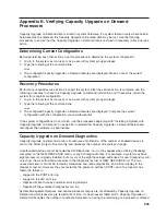
Recovery
Strategy
The
recovery
strategy
consists
of
making
two
calls
to
establish
a
remote
session.
This
solution
is
the
easiest
to
implement
and
allows
more
freedom
for
configuring
your
server’s
serial
ports.
To
set
up
a
remote
terminal
session,
dial
into
the
service
processor
and
start
the
system.
After
the
operating
system
is
loaded
and
initialized,
the
connection
will
be
dropped.
At
this
point,
call
the
server
back
and
the
operating
system
will
answer
and
offer
you
the
login
prompt.
Prevention
Strategy
The
disconnect
is
caused
by
the
operating
system
when
it
initializes
the
Primary
Console.
The
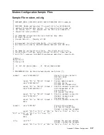
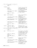
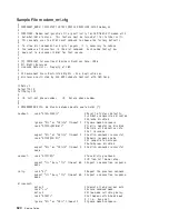
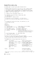
tests
listed
in
“Transfer
of
a
Modem
Session”
on
page
515
are
conducted
with
the
remote
terminal
selected
as
the
primary
console
to
manifest
the
modem’s
response
to
DTR
transitions.
v
If
a
local
ASCII
terminal
or
a
graphics
console
is
to
be
a
permanent
part
of
your
server,
then
make
one
of
them
the
primary
console.
Your
remote
terminal
will
no
longer
experience
the
connection
loss.
v
If
a
local
console
is
not
a
permanent
part
of
your
server,
you
can
still
assign
either
the
unused
graphics
console
or
the
unused
serial
port
as
the
primary
console.
This
gives
you
the
desired
seamless
connection
at
your
remote
terminal.
v
If
you
choose
to
use
the
unused
serial
port
as
the
primary
console,
some
initialization
traffic
will
be
sent
to
any
serial
device
attached
to
that
port.
As
a
result,
that
serial
device’s
connection
and
function
could
be
affected.
These
impacts
may
make
that
port
unattractive
for
devices
other
than
a
temporary
local
ASCII
terminal.
516
Service
Guide
Summary of Contents for RS/6000 Enterprise Server M80
Page 1: ...RS 6000 Enterprise Server Model M80 Eserver pSeries 660 Model 6M1 Service Guide SA38 0571 01...
Page 10: ...x Service Guide...
Page 14: ...xiv Service Guide...
Page 16: ...xvi Service Guide...
Page 22: ...Data Flow 4 Service Guide...
Page 30: ...CEC Card Cage Rear of CEC drawer viewed from top cover removed 12 Service Guide...
Page 84: ...66 Service Guide...
Page 176: ...158 Service Guide...
Page 376: ...358 Service Guide...
Page 430: ...412 Service Guide...
Page 485: ...Chapter 11 Parts Information This chapter contains parts information for the system 467...
Page 486: ...CEC Drawer Card Assembly 9 468 Service Guide...
Page 488: ...CEC Drawer Backplane 5 2a 1 2 3 4 470 Service Guide...
Page 490: ...CEC Drawer Power Supplies 1 2 3 4 5 6 7 8 9 472 Service Guide...
Page 492: ...CEC Drawer Fan Assemblies 2 1 3 4 5 6 8 9 10 11 12 13 7 14 474 Service Guide...
Page 496: ...7 8 9 10 6 1 2 3 4 4 5 478 Service Guide...
Page 508: ...490 Service Guide...
Page 520: ...502 Service Guide...
Page 522: ...504 Service Guide...
Page 526: ...508 Service Guide...
Page 558: ...540 Service Guide...
Page 565: ......


