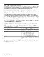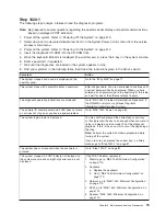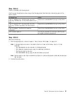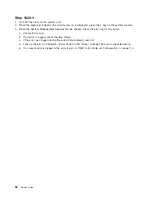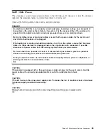
FRU
Isolation
For
a
list
of
error
codes
and
recommended
actions
for
each
code,
see
Chapter
5,
“Error
Code
to
FRU
Index,”
on
page
159.
These
actions
can
refer
to
Chapter
11,
“Parts
Information,”
on
page
467,
Chapter
3,
“Maintenance
Analysis
Procedures
(MAPs),”
on
page
71,
or
provide
informational
message
and
directions.
If
a
replacement
part
is
indicated,
direct
reference
is
made
to
the
part
name.
The
respective
AIX
and
physical
location
codes
are
listed
for
each
occurrence
as
required.
For
a
list
of
locations
codes,
see
“AIX
and
Physical
Location
Code
Reference
Tables”
on
page
31.
To
look
up
part
numbers
and
view
component
diagrams,
see
Chapter
11,
“Parts
Information,”
on
page
467.
The
beginning
of
the
chapter
provides
a
parts
index
with
the
predominant
field
replaceable
units
(FRUs)
listed
by
name.
The
remainder
of
the
chapter
provides
illustrations
of
the
various
assemblies
and
components
which
make
up
these
servers.
Electronic
Service
Agent
for
the
Eserver
pSeries
and
RS/6000
Service
support
for
your
system
can
be
enhanced
through
the
use
of
the
application
program,
Electronic
Service
Agent.
This
application
provides
a
number
of
advantages
for
the
systems
customer,
including
automatic
error
reporting
and
analysis
without
customer
intervention.
The
Electronic
Service
Agent
kit
includes
the
Electronic
Service
Agent
for
Eserver
pSeries
and
RS/6000
CD,
order
number
LCD4–1060,
which
contains
documentation
to
help
you
set
up
and
use
Electronic
Service
Agent.
Using
the
Service
Processor
and
Electronic
Service
Agent
Features
The
service
processor
and
Electronic
Service
Agent
features
protect
users
against
unnecessary
system
downtime
by
advising
support
personnel
(both
internal
and
external)
of
any
unexpected
changes
in
the
system
environment.
In
combination,
the
two
features
provide
a
flexible
solution
to
automated
system
maintenance.
Service
Processor
The
service
processor
runs
on
its
own
power
boundary
and
continually
monitors
hardware
attributes,
the
AIX
operating
system,
and
the
environmental
conditions
within
the
system.
Any
system
failure
which
prevents
the
system
from
returning
to
an
operational
state
(a
fully
functional
AIX
operating
system)
is
reported
by
the
service
processor.
The
service
processor
is
controlled
by
firmware
and
does
not
require
the
AIX
operating
system
to
be
operational
to
perform
its
tasks.
If
any
system
failures
are
detected,
the
service
processor
has
the
ability
to
take
predetermined
corrective
actions.
The
methods
of
corrective
actions
are:
v
Surveillance
v
Call
home
v
AIX
operating
system
monitoring
Surveillance
is
a
function
in
which
the
service
processor
monitors
the
system
through
heartbeat
communication
with
the
system
firmware.
The
heartbeat
is
a
periodic
signal
that
the
firmware
can
monitor.
During
system
startup,
the
firmware
surveillance
monitor
is
automatically
enabled
to
check
for
heartbeats
from
the
firmware.
If
a
heartbeat
is
not
detected
within
a
default
period,
the
service
processor
cycles
the
system
power
and
attempts
to
restart
until
the
system
either
restarts
successfully,
or
a
predetermined
retry
threshold
is
reached.
In
the
event
the
service
processor
is
unsuccessful
in
bringing
the
system
online
(or
in
the
event
that
the
user
asked
to
be
alerted
to
any
service
processor-assisted
restarts),
the
system
can
call
home
to
report
the
error.
The
call
home
function
can
be
initialized
to
call
either
a
service
center
telephone
number,
a
customer
administration
center,
or
a
digital
pager
telephone
number.
The
service
processor
can
be
configured
to
stop
at
the
first
successful
call
to
any
of
the
numbers
listed,
or
can
be
configured
to
call
every
number
provided.
If
connected
to
the
service
center,
the
service
processor
transmits
the
relevant
system
Chapter
2.
Diagnostics
Overview
69
Summary of Contents for RS/6000 Enterprise Server M80
Page 1: ...RS 6000 Enterprise Server Model M80 Eserver pSeries 660 Model 6M1 Service Guide SA38 0571 01...
Page 10: ...x Service Guide...
Page 14: ...xiv Service Guide...
Page 16: ...xvi Service Guide...
Page 22: ...Data Flow 4 Service Guide...
Page 30: ...CEC Card Cage Rear of CEC drawer viewed from top cover removed 12 Service Guide...
Page 84: ...66 Service Guide...
Page 176: ...158 Service Guide...
Page 376: ...358 Service Guide...
Page 430: ...412 Service Guide...
Page 485: ...Chapter 11 Parts Information This chapter contains parts information for the system 467...
Page 486: ...CEC Drawer Card Assembly 9 468 Service Guide...
Page 488: ...CEC Drawer Backplane 5 2a 1 2 3 4 470 Service Guide...
Page 490: ...CEC Drawer Power Supplies 1 2 3 4 5 6 7 8 9 472 Service Guide...
Page 492: ...CEC Drawer Fan Assemblies 2 1 3 4 5 6 8 9 10 11 12 13 7 14 474 Service Guide...
Page 496: ...7 8 9 10 6 1 2 3 4 4 5 478 Service Guide...
Page 508: ...490 Service Guide...
Page 520: ...502 Service Guide...
Page 522: ...504 Service Guide...
Page 526: ...508 Service Guide...
Page 558: ...540 Service Guide...
Page 565: ......

