6.
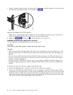
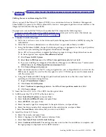
After you install the IVM, finish the installation by accepting the license agreement, checking for
updates, and configuring the TCP/IP connection.
7.
Continue with “Cabling the server and connecting expansion units.”
Cabling the server with keyboard, video, and mouse:
Before you start the system, you might need to connect the keyboard, video, and mouse to the system, if
a graphics card is present.
To connect the keyboard, video, and mouse, complete the following steps:
1.
Locate the graphics card and Universal Serial Bus (USB) ports at the rear of the system. You might
need a connector converter.
2.
Connect the monitor cable to the graphics card.
3.
Connect a keyboard and mouse to the blue USB 3.0 ports.
4.
Power on the console.
5.
Continue with “Cabling the server and connecting expansion units.”
Cabling the server and connecting expansion units
Learn how to cable the server and to connect expansion units.
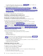
To cable the server and to connect expansion units, complete the following steps:
1.
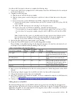
Complete the following steps:
a.
Plug the power cord into the power supply.
b.
Plug the system power cords and the power cords for any other attached devices into the power
source.
c.
If your system uses a power distribution unit (PDU), complete the following steps:
1)
Connect the system power cords from the server and I/O drawers to the PDU with an IEC 320
type receptacle.
2)
Attach the PDU input power cord and plug it into the power source.
3)
If your system uses two PDUs for redundancy, complete the following steps:
v
If your system has two power supplies, attach one power supply to each of the two PDUs.
v
If your system has four power supplies, plug E1 and E2 to PDU A and E3 and E4 to PDU
B
.
Note:
Confirm that the system is in standby mode. The green power status indicator on the
front control panel is flashing, and the dc out indicator lights on the power supplies are
flashing. If none of the indicators are flashing, check the power cord connections.
d.
If your system uses a DC power distribution panel (PDP), complete the following steps:
1)
Connect the system power cables from the server and I/O drawers to the PDP.
2)
If your system uses redundant power supplies, complete the following steps:
v
If your system has two power supplies, attach one power supply to the 'A' feed and the
other to the 'B' feed of the PDP.
v
If your system has four power supplies, attach two power supplies to the 'A' feed and the
other two the 'B' feed of the PDP.
3)
Place the applicable circuit breakers in the ON position.
2.
For information about connecting enclosures and expansion units, see Enclosures and expansion units
(http://www.ibm.com/support/knowledgecenter/POWER8/p8ham/p8ham_kickoff.htm).
Completing the server setup
Learn about the tasks you must complete to set up your managed system.
16
Power Systems: Installing the IBM Power System S822L (8247-22L)
Summary of Contents for S822L
Page 1: ...Power Systems Installing the IBM Power System S822L 8247 22L GI11 9908 06 IBM...
Page 2: ......
Page 3: ...Power Systems Installing the IBM Power System S822L 8247 22L GI11 9908 06 IBM...
Page 16: ...xiv Power Systems Installing the IBM Power System S822L 8247 22L...
Page 62: ...46 Power Systems Installing the IBM Power System S822L 8247 22L...
Page 74: ...58 Power Systems Installing the IBM Power System S822L 8247 22L...
Page 75: ......
Page 76: ...IBM Part Number 01LK526 Printed in USA GI11 9908 06 1P P N 01LK526...


