Procedure
1.
Attach the electrostatic discharge (ESD) wrist strap.
Attention:
v
Attach an electrostatic discharge (ESD) wrist strap to the front ESD jack, to the rear ESD jack, or to
an unpainted metal surface of your hardware to prevent the electrostatic discharge from damaging
your hardware.
v
When you use an ESD wrist strap, follow all electrical safety procedures. An ESD wrist strap is
used for static control. It does not increase or decrease your risk of receiving electric shock when
using or working on electrical equipment.
v
If you do not have an ESD wrist strap, just prior to removing the product from ESD packaging
and installing or replacing hardware, touch an unpainted metal surface of the system for a
minimum of 5 seconds.
2.
Remove the disk drive and fan card. For instructions, see “Removing the disk drive and fan card
from the 8335-GTB” on page 39.
3.
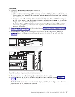
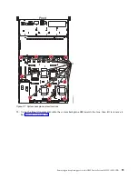
Locate the front USB cable (A) and the power switch and cable (B). They connect between the
system backplane and the power switch along the inside of the system. Label each cable. See
Figure 102.
4.
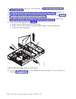
Release each cable from the retaining clip on the inside wall of the system.
5.
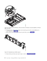
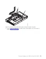
Pressing the latch release on the connector, disconnect the front USB cable (A). See Figure 103 on
page 88.
Note:
The latch release on the connector must be depressed before you unplug the cable. Failure to
do so can damage the cable and the connector.
Figure 102. Location of the power switch and cable connectors
Removing and replacing parts in the IBM Power System S822LC (8335-GTB)
87
Summary of Contents for S822LC
Page 1: ...Power Systems Servicing the IBM Power System S822LC 8335 GTB IBM ...
Page 2: ......
Page 3: ...Power Systems Servicing the IBM Power System S822LC 8335 GTB IBM ...
Page 16: ...xiv Power Systems Servicing the IBM Power System S822LC 8335 GTB ...
Page 204: ...188 Power Systems Servicing the IBM Power System S822LC 8335 GTB ...
Page 242: ...226 Power Systems Servicing the IBM Power System S822LC 8335 GTB ...
Page 243: ......
Page 244: ...IBM ...

