7.
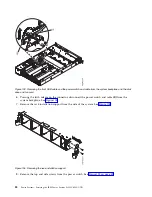
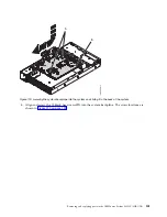
Replace the rack installation support on the side of the system as shown in Figure 112.
8.
Secure each cable in the retaining clip on the inside wall of the system.
9.
Replace the disk drive and fan card. For instructions, see “Replacing the disk drive and fan card in
the 8335-GTB” on page 41.
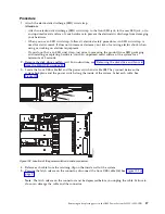
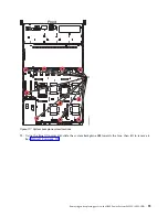
Figure 111. Location of the front USB cable and power switch and cable
Figure 112. Replacing the rack installation support
92
Power Systems: Servicing the IBM Power System S822LC (8335-GTB)
Summary of Contents for S822LC
Page 1: ...Power Systems Servicing the IBM Power System S822LC 8335 GTB IBM ...
Page 2: ......
Page 3: ...Power Systems Servicing the IBM Power System S822LC 8335 GTB IBM ...
Page 16: ...xiv Power Systems Servicing the IBM Power System S822LC 8335 GTB ...
Page 204: ...188 Power Systems Servicing the IBM Power System S822LC 8335 GTB ...
Page 242: ...226 Power Systems Servicing the IBM Power System S822LC 8335 GTB ...
Page 243: ......
Page 244: ...IBM ...


