c.
Return the service hook to its latched position in the bracket.
10.
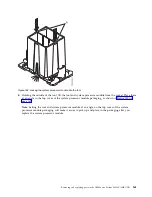
Lightly grip the system processor module that you replaced by the edges and lift it off of the
packaging cover. Align the beveled corner of the module (A) to the corner of the packaging with
triangle (B) and place it in the packaging, as shown in Figure 197. Close the packaging cover.
What to do next
Prepare the system for operation. For instructions, see “Preparing the 8335-GTB system for operation after
you remove and replace internal parts” on page 198.
Figure 196. Tightening the cold plate retainer screw
Figure 197. Placing the system processor module into the packaging
Removing and replacing parts in the IBM Power System S822LC (8335-GTB)
171
Summary of Contents for S822LC
Page 1: ...Power Systems Servicing the IBM Power System S822LC 8335 GTB IBM ...
Page 2: ......
Page 3: ...Power Systems Servicing the IBM Power System S822LC 8335 GTB IBM ...
Page 16: ...xiv Power Systems Servicing the IBM Power System S822LC 8335 GTB ...
Page 204: ...188 Power Systems Servicing the IBM Power System S822LC 8335 GTB ...
Page 242: ...226 Power Systems Servicing the IBM Power System S822LC 8335 GTB ...
Page 243: ......
Page 244: ...IBM ...


