4.
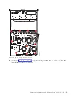
Align and screw the 10 black hex screws (B) into the system backplane. The screw locations are
shown in Figure 147 on page 128.
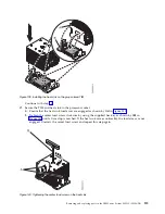
Figure 146. Lowering the system backplane into the system and sliding it to the back of the system.
Removing and replacing parts in the IBM Power System S822LC (8335-GTB)
127
Summary of Contents for S822LC
Page 1: ...Power Systems Servicing the IBM Power System S822LC 8335 GTB IBM ...
Page 2: ......
Page 3: ...Power Systems Servicing the IBM Power System S822LC 8335 GTB IBM ...
Page 16: ...xiv Power Systems Servicing the IBM Power System S822LC 8335 GTB ...
Page 204: ...188 Power Systems Servicing the IBM Power System S822LC 8335 GTB ...
Page 242: ...226 Power Systems Servicing the IBM Power System S822LC 8335 GTB ...
Page 243: ......
Page 244: ...IBM ...


