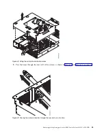
8.
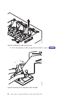
Remove five screws from the bottom of the disk drive and fan card.
9.
Remove one screw from each side of the disk drive and fan card.
10.
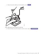
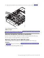
The disk drive and fan card (A) is aligned in the system by using two pins (B). Pivot the disk drive
and fan card away from the fan housing around the pins; then, lift out the card.
11.
Place the disk drive and fan card on the table.
Figure 49. Screw locations for the disk drive and fan card
Figure 50. Removing the disk drive and fan card
40
Power Systems: Servicing the IBM Power System S822LC (8335-GTB)
Summary of Contents for S822LC
Page 1: ...Power Systems Servicing the IBM Power System S822LC 8335 GTB IBM ...
Page 2: ......
Page 3: ...Power Systems Servicing the IBM Power System S822LC 8335 GTB IBM ...
Page 16: ...xiv Power Systems Servicing the IBM Power System S822LC 8335 GTB ...
Page 204: ...188 Power Systems Servicing the IBM Power System S822LC 8335 GTB ...
Page 242: ...226 Power Systems Servicing the IBM Power System S822LC 8335 GTB ...
Page 243: ......
Page 244: ...IBM ...


