About this task
Attention:
For safety, airflow purposes and thermal performance, the service access cover must be
installed and fully seated prior to powering the system on.
Procedure
1.
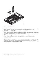
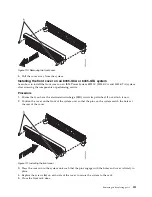
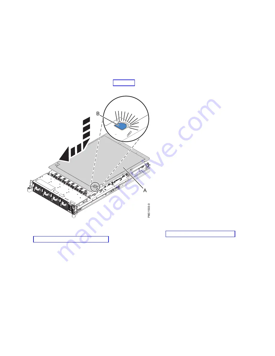
Place the cover (A) on to the system unit such that the alignment pins on the cover are aligned to the
slots on the chassis.
2.
Press down to engage the pins and slide the cover to the front of the system until the blue release
latch (B) locks in to place, as shown in Figure 109.
3.
Replace the power supplies into the chassis. For instructions, see “Replacing a power supply in the
8335-GCA or 8335-GTA” on page 53.
Removing the front cover from an 8335-GCA or 8335-GTA system
Learn how to remove the cover from an IBM Power System S822LC (8335-GCA and 8335-GTA) system so
that you can access the components or perform service.
Procedure
1.
If necessary, open the front rack door.
2.
Ensure that you have the electrostatic discharge (ESD) wrist strap attached. If not, attach it now.
3.
Loosen the screws (A) located on both sides of the cover to disengage the cover from the system unit.
Figure 109. Installing the service access cover
110
Servicing the IBM Power System S822LC (8335-GCA or 8335-GTA)
Summary of Contents for S822LC
Page 1: ...Power Systems Servicing the IBM Power System S822LC 8335 GCA or 8335 GTA IBM...
Page 2: ......
Page 3: ...Power Systems Servicing the IBM Power System S822LC 8335 GCA or 8335 GTA IBM...
Page 16: ...xiv Servicing the IBM Power System S822LC 8335 GCA or 8335 GTA...
Page 134: ...118 Servicing the IBM Power System S822LC 8335 GCA or 8335 GTA...
Page 145: ...Notices 129...
Page 146: ...IBM Printed in USA...


