v
E: Indicators -
to display status for alerts (amber), system ID (blue), and power (green) respectively.
v
F: Power switch -
to power the unit on or off.
v
G: Management interfaces (2 GbE NICs) -
use Management port 0 to manage the SiteProtector
appliance; management port 1 is unused. The Management port handles all network communication.
v
H: VGA video port -
for external monitor.
Note:
Use the VGA port when you perform a procedure that requires a monitor to be attached, such as
restoring the SiteProtector SP3001 appliance to a supported state as covered in “Restoring factory
defaults” on page 25.
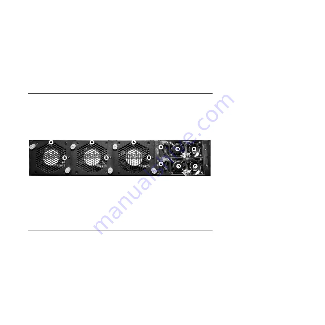
The SiteProtector SP3001 appliance back panel
The SiteProtector SP3001 appliance back panel includes cooling fans, fan status indicators, power
connections, and power supplies.
SiteProtector SP3001 appliance back panel
The following figure shows the SiteProtector SP3001 appliance back panel:
Back panel features
The following list describes the back panel features.
v
A: Cooling fans (3)
v
B: Cooling fan status indicators (3)
v
C: Power connections (2)
v
D: Power supplies (4)
Connecting the SiteProtector SP3001 appliance
Follow these instructions to connect the SiteProtector SP3001 appliance.
Procedure
1.
Connect the power cords to the SiteProtector SP3001 appliance and to the power source.
Important:
You must connect both power cords to the SiteProtector SP3001 appliance to prevent
warning signals from sounding.
2.
Connect the Ethernet cable from the network to management port 0.
3.
Turn on the SiteProtector SP3001 appliance. “IBM Security SiteProtector SP3001” appears on the LCD
panel.
Note:
It may take several minutes for this message to appear.
Figure 2. SP3001 appliance back panel
Chapter 3. Connecting and configuring the SiteProtector SP3001 appliance
13
Summary of Contents for SP3001
Page 4: ...iv SiteProtector System SP3001 Hardware Configuration ...
Page 12: ...6 SiteProtector System SP3001 Hardware Configuration ...
Page 16: ...10 SiteProtector System SP3001 Hardware Configuration ...
Page 26: ...20 SiteProtector System SP3001 Hardware Configuration ...
Page 30: ...7 Close the Remote Desktop session 24 SiteProtector System SP3001 Hardware Configuration ...
Page 32: ...26 SiteProtector System SP3001 Hardware Configuration ...
Page 42: ...36 SiteProtector System SP3001 Hardware Configuration ...
Page 46: ...40 SiteProtector System SP3001 Hardware Configuration ...
Page 48: ...42 SiteProtector System SP3001 Hardware Configuration ...
Page 49: ......
Page 50: ... Printed in USA ...


