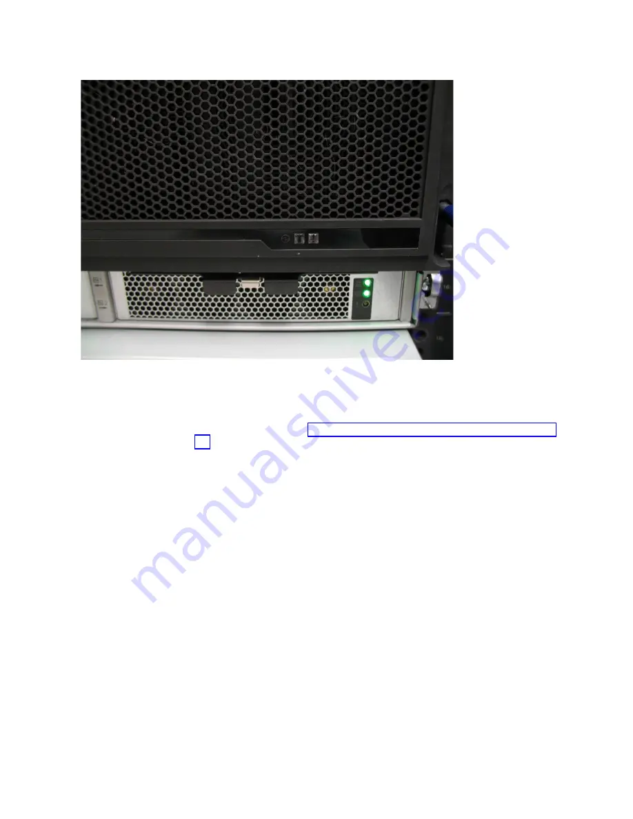
Replace the fascia
4.
To reinstall the front or PSU fascia, or replace them with parts from FRU stock,
follow the procedure in “Installing or replacing the fascia: 2076-92F” on page
77.
Removing and installing a SAS cable: 2076-92F
Use the following procedures to attach SAS cables to the 2076-92F enclosure during
the initial installation process. You can also remove a faulty SAS cable and replace
it with a new one received from FRU stock.
About this task
Be careful when you are replacing the hardware components that are located in the
back of the system. Do not inadvertently disturb or remove any cables that you are
not instructed to remove.
If you replace more than one cable, record which two ports, canisters, and
enclosures each cable connects, so you can match the connections with the
replacement cables. The system cannot operate if the SAS cabling to the expansion
enclosure is incorrect.
When the 2076-92F expansion enclosure is installed in the rack, the expansion
canisters are upside down. The input cable connects to the right port (port 1) on
the expansion canister. The output cable connects to the left port (port 2) on the
canister.
Procedure
Removing a SAS cable
svc01032
Figure 77. Fascia removed from the PSUs
Chapter 2. Installing the Storwize V7000 Gen2 and Storwize V7000 Gen2+ hardware
85
Summary of Contents for StorVize V7000 Gen2
Page 8: ...viii Storwize V7000 Gen2 and Gen2 Quick Installation Guide ...
Page 24: ...xxiv Storwize V7000 Gen2 and Gen2 Quick Installation Guide ...
Page 36: ...12 Storwize V7000 Gen2 and Gen2 Quick Installation Guide ...
Page 166: ...142 Storwize V7000 Gen2 and Gen2 Quick Installation Guide ...
Page 174: ...150 Storwize V7000 Gen2 and Gen2 Quick Installation Guide ...
Page 176: ...152 Storwize V7000 Gen2 and Gen2 Quick Installation Guide ...
Page 184: ...160 Storwize V7000 Gen2 and Gen2 Quick Installation Guide ...
Page 187: ......
Page 188: ...IBM Printed in USA GC27 6500 08 ...


