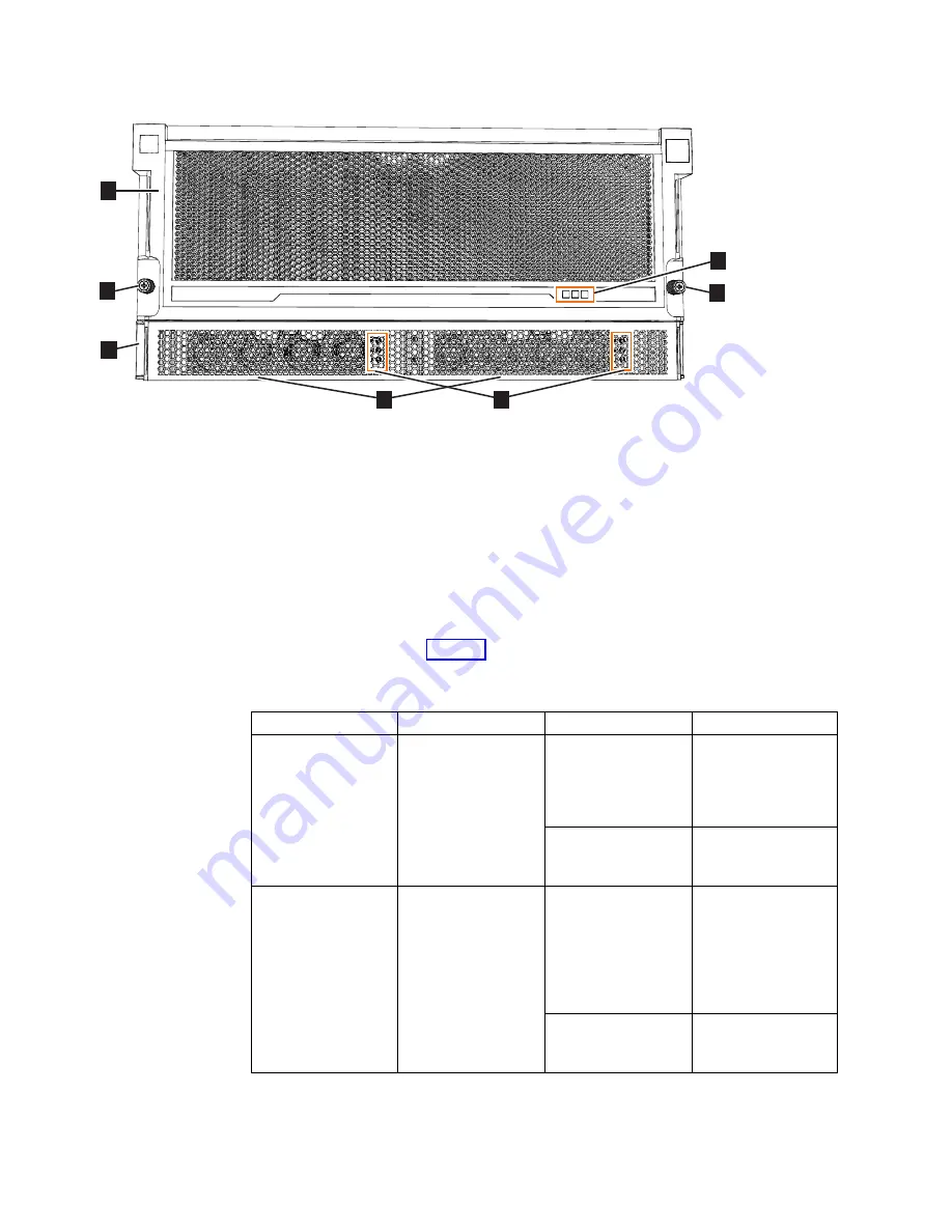
▌1▐
Display panel LEDs
▌2▐
Rack retention thumb screws
▌3▐
Power supply unit LEDs
▌4▐
Power supply units (PSUs)
▌5▐
PSU fascia (1U)
▌6▐
Front fascia (4U)
The display panel (
▌1▐
) contains three LEDs that describe the operational status of
the expansion enclosure. Table 15 describes the function and meaning of the LEDs
on the front display panel.
Table 15. Display panel LEDs
Function
Color
Status
Description
Power
Green
On
The expansion
enclosure power is
on; this LED is
controlled by the
expansion enclosure.
Off
The expansion
enclosure power is
off.
Identify
Blue
On
Identifies the
expansion enclosure;
this LED is controlled
by the system. Use
the management GUI
or service interface to
identify an enclosure.
Off
The expansion
enclosure is
operating normally.
svc00960
1
2
5
6
2
3
4
Figure 120. LEDs on the front of the expansion enclosure
132
Storwize V7000 Gen2 and Gen2+: Quick Installation Guide
Summary of Contents for StorVize V7000 Gen2
Page 8: ...viii Storwize V7000 Gen2 and Gen2 Quick Installation Guide ...
Page 24: ...xxiv Storwize V7000 Gen2 and Gen2 Quick Installation Guide ...
Page 36: ...12 Storwize V7000 Gen2 and Gen2 Quick Installation Guide ...
Page 166: ...142 Storwize V7000 Gen2 and Gen2 Quick Installation Guide ...
Page 174: ...150 Storwize V7000 Gen2 and Gen2 Quick Installation Guide ...
Page 176: ...152 Storwize V7000 Gen2 and Gen2 Quick Installation Guide ...
Page 184: ...160 Storwize V7000 Gen2 and Gen2 Quick Installation Guide ...
Page 187: ......
Page 188: ...IBM Printed in USA GC27 6500 08 ...


