v
4
Top rail location pin hole
3.
Align the bottom of the rail with the bottom of the two rack units. Insert the
rail location pins
1
and
4
through the holes in the rack cabinet.
4.
Insert a clamping screw into the rack mounting hole
3
between the rail
location pins.
5.
Tighten the screw to secure the rail to the rack.
6.
Working from the rear of the rack cabinet, extend the rail that you secured to
the front to align the bottom of the rail with the bottom of the two rack units.
Note:
Ensure that the rail is level between the front and the back.
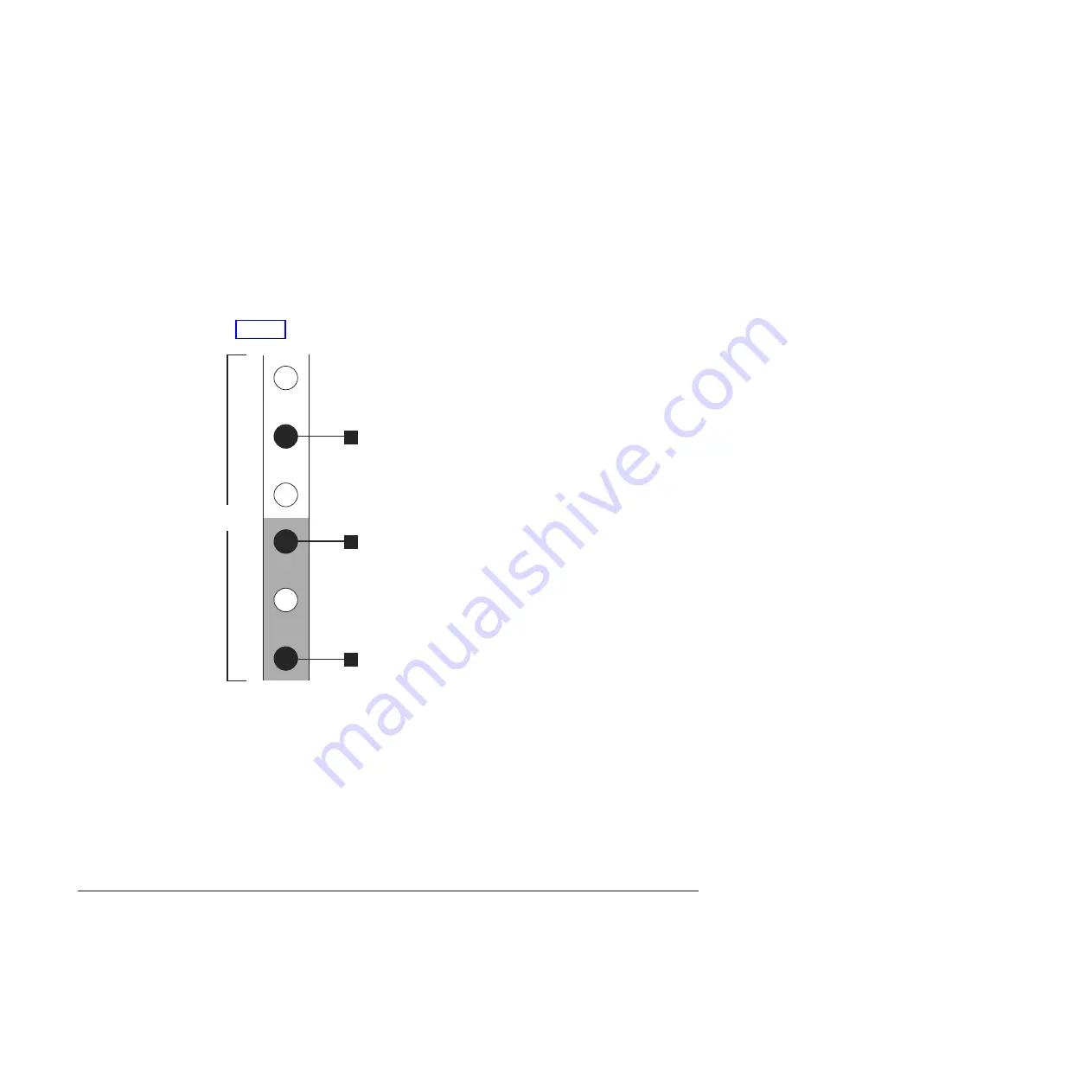
Figure 5 shows two rack units with the back mounting holes identified.
v
1
Bottom rail location pin hole
v
2
Rack mounting screw hole
v
3
Top rail location pin hole
7.
Insert the rail location pins through the holes
1
and
3
in the rack cabinet.
8.
Insert a clamping screw into the rack mounting hole
2
between the rail
location pins.
9.
Tighten the screw to secure the rail to the rack from the back side.
10.
Repeat the steps to secure the opposite rail to the rack cabinet.
11.
Repeat the procedure for each additional enclosure.
Installing the enclosures
Follow this procedure to install an enclosure into a rack.
svc00696
2 Units
1
2
3
Figure 5. Hole locations in the back of the rack
10
IBM Storwize V7000: Expansion Enclosure Installation Guide
Summary of Contents for Storwize V7000
Page 20: ...2 IBM Storwize V7000 Expansion Enclosure Installation Guide...
Page 26: ...8 IBM Storwize V7000 Expansion Enclosure Installation Guide...
Page 36: ...18 IBM Storwize V7000 Expansion Enclosure Installation Guide...
Page 38: ...20 IBM Storwize V7000 Expansion Enclosure Installation Guide...
Page 42: ...24 IBM Storwize V7000 Expansion Enclosure Installation Guide...
Page 43: ......
Page 44: ...Part Number 00AR336 Printed in USA GC27 4234 02 1P P N 00AR336...


