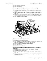
4.
Remove
the
cash-drawer
propulsion
spring
by
pushing
the
spring
retainer
back,
and
then
slide
the
spring
up
and
out
of
its
mounting
slots
(see
Figure
70
on
page
83).
5.
Remove
the
latch
plate
bracket
by
removing
the
screw
in
the
cam
pivot
post
and
the
screw
in
the
pawl
pivot
post
(see
Figure
70
on
page
83).
6.
Remove
the
cam
spring
by
lifting
the
ends
of
the
small
posts
on
the
cam
and
the
pawl
(see
Figure
70
on
page
83).
7.
Spread
apart
the
two
pawl
latches
that
hold
the
pawl
on
the
pivot
post,
while
lifting
the
pawl
off
the
post
(see
Figure
70
on
page
83).
8.
Spread
apart
the
two
cam
latches
that
hold
the
cam
on
the
pivot
post,
while
lifting
the
cam
off
the
post
(see
Figure
70
on
page
83).
9.
Remove
the
three
screws
that
retain
the
card
assembly
and
remove
the
card
assembly
(see
Figure
70
on
page
83).
To
replace
the
components
of
the
latch
and
sensor
assembly,
reverse
this
procedure.
Removing
and
replacing
the
keylock
insert
A
Lock
insert
and
keys.
B
Aligner.
This
tool
is
used
to
ensure
that
the
slot
at
the
bottom
of
the
lock
cylinder
aligns
with
the
lock
insert
being
installed.
For
the
cash
drawer,
the
arrow
on
the
aligner
should
point
up.
(The
arrow
points
in
different
directions
for
other
types
of
devices.)
C
Brass
installation-removal
key.
D
Blank
lock
installation
handle.
E
Blank
lock
insert.
To
remove
the
keylock
insert:
1.
The
lock
must
be
in
the
unlocked
position.
2.
Insert
the
brass
installation-removal
key
fully
into
the
lock
until
it
clicks
into
place.
3.
Pivot
the
brass
key
slightly
downward
while
pulling
the
lock
insert
out
of
the
cylinder
until
the
insert
is
disengaged
from
the
cylinder.
Note:
The
brass
key
and
the
lock
insert
come
out
of
the
lock
cylinder
together.
Pressing
downward
or
sideways
on
the
brass
key
as
you
pull
makes
it
easier
for
the
lock
insert
to
come
out
along
with
the
brass
key.
4.
Remove
the
brass
key.
To
replace
the
keylock
insert:
1.
The
lock
insert
fits
all
the
way
into
the
lock
cylinder
only
when
the
slot
in
the
bottom
of
the
cylinder
and
the
lug
on
the
end
of
the
insert
are
aligned.
If
necessary,
insert
the
aligner
tool
(see
Figure
71)
into
the
lock
cylinder
and
A
B
C
D
E
Figure
71.
Lock
accessories
Removing
and
replacing
FRUs
Updated
October,
2008
84
SurePOS
500
Model
514
Summary of Contents for SurePOS 514
Page 2: ......
Page 8: ...Updated October 2008 vi SurePOS 500 Model 514 ...
Page 12: ...Updated October 2008 x SurePOS 500 Model 514 ...
Page 16: ...Updated October 2008 xiv SurePOS 500 Model 514 ...
Page 20: ...Figure 2 Serial number location Updated October 2008 4 SurePOS 500 Model 514 ...
Page 32: ...Installing the IBM SurePOS 500 Model 514 Updated October 2008 16 SurePOS 500 Model 514 ...
Page 64: ...Installing additional peripheral devices Updated October 2008 48 SurePOS 500 Model 514 ...
Page 68: ...Updated October 2008 52 SurePOS 500 Model 514 ...
Page 102: ...Updated October 2008 86 SurePOS 500 Model 514 ...
Page 138: ...Updated October 2008 122 SurePOS 500 Model 514 ...
Page 143: ...IBM IBM GA27 4004 GA27 4004 Updated October 2008 Appendix D Safety information 127 ...
Page 152: ...Updated October 2008 136 SurePOS 500 Model 514 ...
Page 156: ...Updated October 2008 140 SurePOS 500 Model 514 ...
Page 158: ...Updated October 2008 142 SurePOS 500 Model 514 ...
Page 161: ......


