a.
Attach
the
keyboard
cable
A
to
the
IBM
PS/2
®
port
on
the
rear
connector
panel.
b.
Place
the
keyboard
on
the
integration
tray
while
pushing
the
excess
keyboard
cable
back
under
the
filler
panel.
14.
Prepare
the
distributed
customer
display
to
be
installed
on
an
integration
tray.
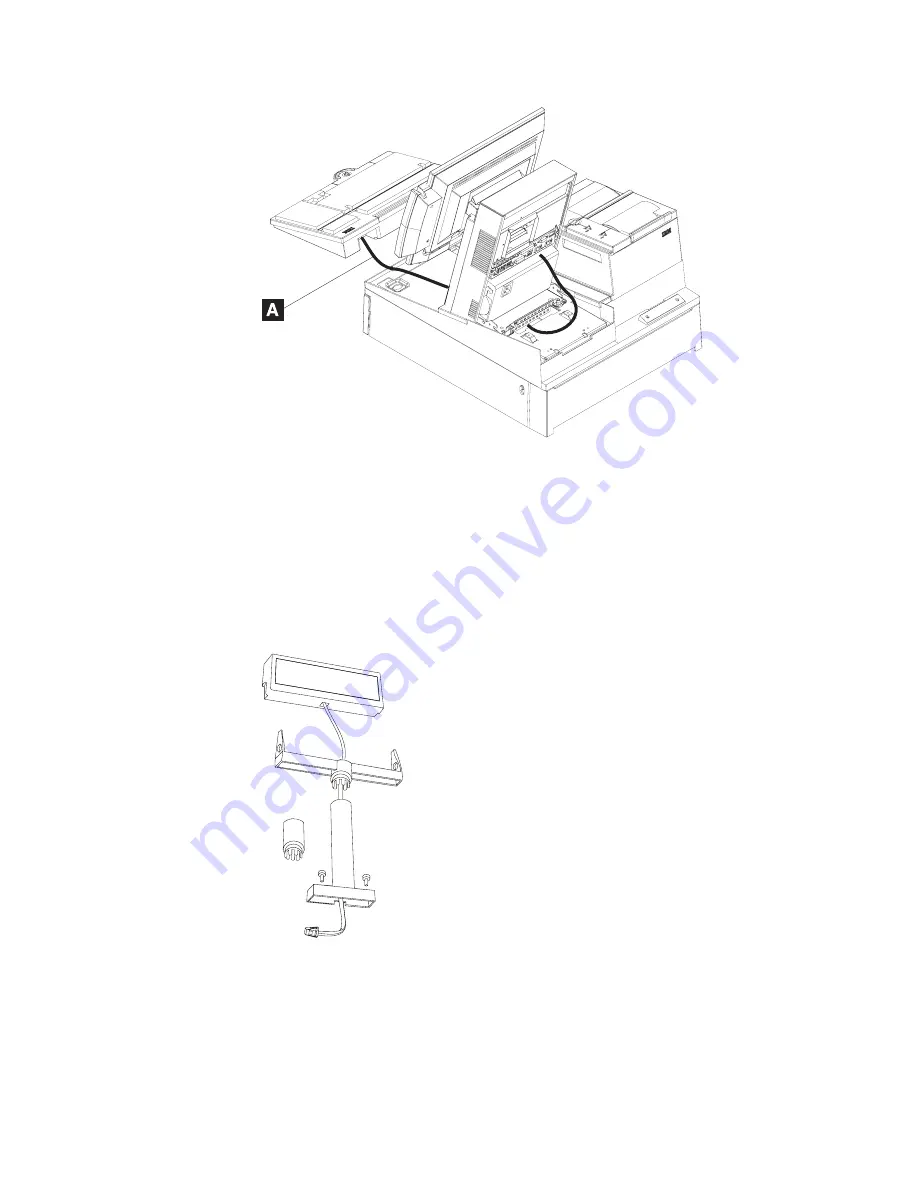
a.
Route
the
distributed
customer
display
cable
through
the
mounting
post
(and
post
extension,
if
used)
and
plug
the
cable
into
the
display.
b.
Attach
the
character
display’s
top
to
its
post
by
pressing
the
display
down
on
the
post
until
it
snaps
into
place.
15.
To
install
a
distributed
customer
display
or
an
APA
display,
perform
the
following
steps:
Figure
30.
Installing
the
keyboard
onto
the
integration
tray
Figure
31.
Attaching
the
distributed
customer
display
cable
Mounting
the
SurePOS
500
Model
514
Updated
October,
2008
Chapter
3.
Mounting
the
SurePOS
500
Model
514
39
Summary of Contents for SurePOS 514
Page 2: ......
Page 8: ...Updated October 2008 vi SurePOS 500 Model 514 ...
Page 12: ...Updated October 2008 x SurePOS 500 Model 514 ...
Page 16: ...Updated October 2008 xiv SurePOS 500 Model 514 ...
Page 20: ...Figure 2 Serial number location Updated October 2008 4 SurePOS 500 Model 514 ...
Page 32: ...Installing the IBM SurePOS 500 Model 514 Updated October 2008 16 SurePOS 500 Model 514 ...
Page 64: ...Installing additional peripheral devices Updated October 2008 48 SurePOS 500 Model 514 ...
Page 68: ...Updated October 2008 52 SurePOS 500 Model 514 ...
Page 102: ...Updated October 2008 86 SurePOS 500 Model 514 ...
Page 138: ...Updated October 2008 122 SurePOS 500 Model 514 ...
Page 143: ...IBM IBM GA27 4004 GA27 4004 Updated October 2008 Appendix D Safety information 127 ...
Page 152: ...Updated October 2008 136 SurePOS 500 Model 514 ...
Page 156: ...Updated October 2008 140 SurePOS 500 Model 514 ...
Page 158: ...Updated October 2008 142 SurePOS 500 Model 514 ...
Page 161: ......


