background image

Summary of Contents for System/32

Page 1: ...Maintenance Library SYSTEM 3 Introduction and Maintenance SY31 0373 4...

Page 2: ...rary System 32 Theory Diagrams SY31 0346 In addition refer to the System 32 Diagnostic User s Service Guide for further information on system diagnostic procedures Fifth Edition May 1977 This is a maj...

Page 3: ...ENCE 1 10 2 2 10 Shock Mount Top One 2 24 1 11 0 MICRO INTERRUPTS 1 11 2 2 11 Shock Mounts Bottom Two 2 24 1 12 0 SYSTEM PARITY CHECKING AND 2 3 0 CABLE AND CARD LOCATIONS 2 26 PARITY GENERATION 1 12...

Page 4: ...erlock Switch 4 18 Type Belt Transducer 4 5 4 2 2 2 Print Unit Throat Interlock Switch 4 19 Ribbon Drive 4 6 4 2 2 3 End of Forms Interlock Switch 4 19 Type Belt Drive 4 6 4 2 3 Thermal Switch 4 20 Ca...

Page 5: ...51pm 4 52 Paper Clamps 4 90 4 2 35 1 For Ribbon Shields Without Guides 4 52 4 5 3 Checking 285 Ipm 4 91 4 2 35 2 For Ribbon Shields With Guides 4 52 Forms Jam Check 4 91 4 2 36 Ribbon Shield 50 100 an...

Page 6: ...inds 4 113 4 6 49 Lower Paper Guide To Hammer 4 6 14 Type Belt Drive Pulley Assembly 4 114 Clearance 4 152 4 6 15 Type Belt Motor 4 115 4 7 0 LOCATIONS 285Ipm 4 153 4 6 16 Type Belt Positioning Roller...

Page 7: ...IPL Switch 7 6 7 2 3 PROC INTERRUPT Lights 7 6 7 2 4 RESET Key 7 6 7 2 5 ADDRESS DATA DISPLAY DATA Switches 7 7 7 2 6 CLOCK Light 7 7 7 2 7 FORCE CLOCK Switch 7 7 7 2 8 CHECK Switch 7 7 7 2 9 CE STAR...

Page 8: ...ure Rolls 9 18 10 3 0 1200 BPS INTEGRATED MODEM 10 4 9 2 7 Forms Tractor Unit 9 19 10 3 1 Transmit Level Adjustment 10 4 9 2 8 Forms Tractor Unit Chain Cover 9 19 10 3 1 1 WT PSN Line Plate and Cable...

Page 9: ...eset B 2 First Advance Pulse A B Generated by Adapter B 2 Second Advance Pulse AB B 3 Third Advance Pulse A B B 3 33FD STEPPER MOTOR B 4 APPENDIX C INSTALLATION INSTRUCTIONS C 1 SYSTEM 32 INSTALLATION...

Page 10: ...x...

Page 11: ...s IPL Initial program load reg Register comp compare IR Incident report rep Repeat cps Characters per second irpt Interrupt RPG Report program generator CPU Central processing unit processing rpm Revo...

Page 12: ...VFC Vertical forms control VFO Variable frequency oscillator vol Volume VOL ID Volume identification VOM Volt ohm meter VTL Vendor technology logic VTOC Volume table of contents WR Work register WTC W...

Page 13: ...hat are not approved by IBM 9 Do not use tools or test equipment that is not approved by IBM 10 Replace worn or broken tools and test equipment 11 Do not lift a load that you and your man ager feel wo...

Page 14: ...xiv...

Page 15: ...either the serial printer or the belt printer The serial printer has 132 print positions and uses a 64 character set It is a 7 x 7 wire matrix printer The serial printer is available in four models 1...

Page 16: ...r I I I I L _______ J Processing Unit Channel Attachments Control Storage and Main Storage Keyboard Top View Printer ffa OtlDCCDc J DC I DDOCOOOCC I tlDOOooaS otJ DO Doccn DO CU I DC 0 DCC I Operator...

Page 17: ...nel as used in this system refers to the internal interface between the processor and logic for control of I O function The channel contains a port through which part of this control passes Display Ke...

Page 18: ...ut Low I f 1 4 T 1f I I II i 0 5 7 o 7 8V 15 8 7 715 IX High V High I X Low I I V Low 1 r JI r t Adr I AdrSw Comp l Adr I Comp V f ALU ALU I High Low I 7 I 0 8 15 I I 7 7 VV I pB r I Event Ind Display...

Page 19: ...1 5 0 CHANNEL DATA FLOW Channel Sys Bus Out Low Command Bus Out Port Data Bus Out Att Device Gate Port Data Bus in Control Lines Processing Unit Channel SBI Introduction 1 5...

Page 20: ...ta in main storage Channel operations The microprogram must be loaded into control storage initial microprogram load before any processing can begin The microprogram can be loaded from either the disk...

Page 21: ...the disk I O area of control storage printer instructions by the printer I O area and keyboard and display screen instructions by the keyboard CRT I O area The I O interrupt handler processes micro in...

Page 22: ...mined to be positive negative or zero The PCR also contains results from compare or test mask instructions 1 8 6 Storage Data Register SDR The SO R is a 16 bit register that serves as an inter mediate...

Page 23: ...e return address when a branch and link instruction is executed The third group hex address 10 17 is used by micro interrupt level 1 disk and the fourth group hex address 18 1 F is used by micro inter...

Page 24: ...Storage and I O Wrap Tests Load DCP 1 10 1 10 0 EVENT INDICATOR SEQUENCE The LOAD light and all nine event indicator lights high byte display on CE panel are turne on when LOAD is pressed When LOAD i...

Page 25: ...Micro interrupt level 3 can be used by the mag card unit magnetic character reader or data recorder attachment features Micro interrupt level 0 shares a set of work reg isters with the main program le...

Page 26: ...g and parity generating sta tions are illustrated in the diagram on this page 151 i Control Storage 2 bytes Main Storage 1 byte I SAR CK 1 Parity predict circuits check the ALU portion of the processi...

Page 27: ...PC PG PC Parity checked PG Parity generated Sense Int lVl Cycle Status Steal In No PC PG in Channel PC N A N A N A PG2 PG N A Note Attachments generate a parity bit on the OBI when responding to a Ju...

Page 28: ...is procedure program that resides on the CE diskette Essentially two types of error information are recorded for each device and the processing unit error history and error count In addition to the er...

Page 29: ...TIONS Disk Disk Input Output Gate A Al G Cable Tower Section 3 33F D Input Output Connector Front View Display Section 5 Printer Belt Section 4 Serial Section 9 Operator Control Panel Section 7 Introd...

Page 30: ...CBA E 1 1 I 1 1 3 N1 I M1 III I I I 1 EDCBA EDCBA ED 1 K11 J1 I Hl 1 1 SAl EDCBA EDCBA 1 16 Gli F1 1 El 101 Cl 1 B1 JA1 I I I I 1 1 I AIEDCBAI EDCSA E EDCSA I EDCBA ED 1 1 I Card Column VUTS Rap NM LK...

Page 31: ...ws and plastic clamps in the new style subframe the wires and cables are guided with slots and guides that are integral parts of the subframe casting 2 1 3 Grounding The subframe is grounded by a grou...

Page 32: ...ounding temperature changes 2 1 5 Disk Spindle The disk spindle assembly is mounted in a housing in the back of the disk enclosure The housing is sealed to prevent contaminants from being drawn into t...

Page 33: ...he landing zone position The lock prevents the actuator from moving during shipping installation or removal of the disk enclosure Back View 2 1 9 Actuator Position Indicator When the edge of the actua...

Page 34: ...c Service User s Guide Cross Section of Disk Behind Home Servo Tracks The servo tracks of the disk contain prewritten patterns on the outer half of the disk These pat terns correspond to each data tra...

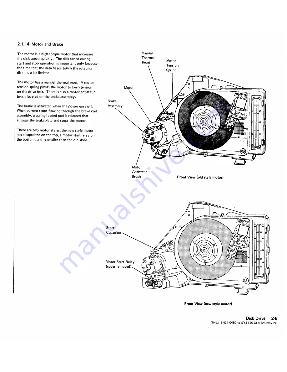
Page 35: ...ush located on the brake assembly The brake is activated when the power goes off When current stops flowing through the brake coil assembly a spring loaded pad is released that engages the brakeplate...

Page 36: ...g the circuits from read to write Start write gap SWG is 2 bytes of hex FF that allows time to switch the circuits from read to write Flag Byte Data Field CRC Bfr 2 EWG Bits Meaning 7 Bytes Unassigned...

Page 37: ...he disk drive cannot seek or recalibrate In this case if power is dropped the actuator retracts File Ready The disk drive either fails to go ready or goes not ready after power up for any of the follo...

Page 38: ...n the actuator is decel erated and stops at the required destination At this point track following signals take control 2 1 17 Recalibrate Operation The recalibrate operation moves the heads across th...

Page 39: ...erefore shows the signal received from the servo tracks when the data heads are correctly positioned over a data track Cross Section of Disk Behind Home If the data heads move off track the servo trac...

Page 40: ...CAUTION Take extreme care not to bend or break the pins when removing or inserting cards Bent or broken pins make it necessary to replace the entire disk enclosure The card sockets are located on the...

Page 41: ...This page intentionally left blank Disk Drive 2 11...

Page 42: ...kets 5 Lnck the actuator with the actuator lock 1m by moving the handle to ON 6 Remove the helt guard by loosening the two screws II and lifting it off 7 Loosen the two screws mthat hold the spindle l...

Page 43: ...m smooth side against the pulleys Center the belt on the pulleys 10 Loosen the two screws holding the spindle locking arm III and slide the locking arm away from the disk spindle See 2 1 3 Grounding...

Page 44: ...ease tension on the belt and remove the belt m 8 Remove the motor wires from DETB1 II terminal 1 blue wire terminal 2 white wire and terminal 3 two green yellow wires 9 Remove the brake wires from DET...

Page 45: ...stall the cable straps m if present that a pressure of 60 25 20 grams on the slip the tapered pin on the mounting bracket hold the motor brake and ac cables center of the disk spindle Adjust the brush...

Page 46: ...move the belt m Remove the motor wires from 0 ETB1 ri terminal 1 blue wire terminal 2 white wire and terminal 3 two green yellow wires 9 Remove the brake wires from OETB1 Ii terminal 5 black wire and...

Page 47: ...raps m if present that hold the motor brake and ac cables 10 CAUTION Make sure the belt does not contact the disk speed transducer Replace the belt II smooth side of the belt against the pulleys Cente...

Page 48: ...embly 3 Mark the wires then disconnect them from the relay 4 Remove the two relay holding screws and lift out the relay Replacement 1 Install the motor start relay and holding screws 2 Connect the wir...

Page 49: ...This page intentionally left blank Disk Drive 2 16 3 TN L SN31 0487 to SY31 0373 4 25 Nov 77...

Page 50: ...ocking arm 7 Lift the motor to release the tension on the belt and remove the belt III 8 Remove the brake wires from the right side DETB1 m terminal 5 black wire and terminal 6 yellow wire 9 Remove th...

Page 51: ...mare aligned with the three studs II on the brake coil Note The hazard label should be up and tq the right and the cables from the motor and brake should run together at the bot tom left when viewed f...

Page 52: ...1 mm 13 Turn power on at the mainline switch and at the operator control panel 14 DANGER 220 Vac present on TB1 With the brake coil energized the gap 0 between the brake pad and the brake plate should...

Page 53: ...J Ilmo 008 inch JL 0 002 inch 0 203 mm D 0 051 mm Disk Drive 2 19...

Page 54: ...off at the back of the mach ine Lock the actuator with the actuator lock mby moving the handle to ON Remove the belt guard by loosening the two screws I J and Iifting it off Remove the two screws CJ h...

Page 55: ...osen the transducer clamping screw g Make sure the tab on the transducer is in the slot in the bracket Replace the transducer assembly with the two mounting screws Ii Adjust the transducer for a gap o...

Page 56: ...2 22 This page intentionally left blank...

Page 57: ...ft the spring off the stud 6 For new style motor tension springs only Remove one of the insulating washers from the roller end of the spring assembly and slide off the spring Replacement 1 For new sty...

Page 58: ...6 Loosen the two screws 13 that hold the spindle locking arm and slide the locking arm away from the disk spindle Make sure the antistatic brush is contacting the center of the spindle Note If there i...

Page 59: ...ocking arm away from the disk spindle Make sure the spindle antistatic brush is contacting the center of the spindle Note If there is a wear crater on the spin dle antistatic brush realign the crater...

Page 60: ...le ground pin is D W1A4DOB Read Preamp and Write Driver W1B3 CAUTION Write select Write gate 1 Write current on 6V Card interlock line 24V W1A5 Read data automatic gain control and data detector Write...

Page 61: ...Minus 12V Current Regulators Read Write Scan Data Cycle Steal Control Data Unsafe Detection Phase Lock Oscillator Contro A2D4 Servo Velocity Control Interlock Singleshots I 0 0 0 0 D 0 0 0 0 0 0 0 0...

Page 62: ...2 28 This page intentionally left blank...

Page 63: ...osed in an 8 inch x 8 inch 203 2 mm x 203 2 mm plastic cartridge The 33FD reads data from the diskette or writes data on the diskette The disk ette drive positions the read write head to any of the 77...

Page 64: ...to the processing unit via the 33FD attachment When the cover is closed the spring loaded collet centers and clamps the diskette to the drive hub Head Load Actuator Assembly The head load actuator as...

Page 65: ...er motor shaft The stepper motor shaft turns in increments of 90 degrees in either direction under the control of access pulses The stepper motor wheel en gages the leadscrew wheel When the stepper mo...

Page 66: ...tracks are divided into 26 sectors each record contains 128 bytes Thus diskettes that contain 74 data tracks divided into eight sectors per track have a capacity of 303 104 bytes of data those divided...

Page 67: ...ntrol field ______ I L L __ Field Track Address 2 3 Record Address 4 Record Length Gap 2 contains 11 bytes of hex FF The eRe cyclic redundancy check bytes are generated during a write operation The st...

Page 68: ...for 150 ms minimum m 50 ms for travel and 100 ms to stabilize Access 0 1 3 For each access command the stepper motor II rotates the leadscrew Ii 90 degrees clockwise or counterclockwise This moves the...

Page 69: ...66 6 ms I Nominal CI I80 ms I i 9 1 I I ______________ D I_JI W I 1 1 1 ____________________ Lines Energized Leadscrew Rotation 1 9 I I Head Location I I J Track 0 2 I 3 I 4 I 5 6 1 Access 0 1 Access...

Page 70: ...of the data track as shown in the following illustration The edges are erased to prevent reading adjacent tracks during a read operation ReadIWrite Head te DATA Erased 1 fi Data Motion vu Erase Heads...

Page 71: ...a light film IBM No 6 oil when the head carriage is replaced To avoid damage to the head Clean only with isopropyl alcohol and a clean cloth after removing the diskette 3 2 10 3 2 2 Tools CE Alignment...

Page 72: ...velopes and store in the following environment Temperature 50 to 125 F 10 0 to 51 5 C Relative humidity 8 to 80 Maximum wet bulb 85 F 29 4 C If a diskette was exposed to temperatures out side of the m...

Page 73: ...e of the screws protruding through the plate at the left side of the 33FD near the drive pulley 3 Turn the locks II remove the 33FD and mounting frame from the machine 4 Disconnect the cables if power...

Page 74: ...placing cover screws posi tion actuator bail under pressure pad arm 11 3 12 3 2 8 Cover Assembly Removal and Replacement CAUTION Do not allow pressure pad arm to snap against the head 1 2 3 Turn power...

Page 75: ...ld Style File Control Card Erase Current 5 Vdc r Preamp TP2 Head Load r T r 7 T Head Engage r t Write Data MC 1 MC 2 MC 3 MC O T i Preamp TP1 Ground LED Current Access 0 I New Style File Control Card...

Page 76: ...n until top clears baseplate then slide assembly out CAUTION Do not allow pressure pad arm to snap against the head 11 Remove top bearing and both stops from leadscrew Replacement Note If the leadscre...

Page 77: ...ling limits 5 Loosen two motor mounting clamps and remove the drive motor Il 6 Remove the drive pulley Ii Replacement 1 Replace the drive pulley Align setscrew with flat surface on shaft and tighten D...

Page 78: ...3 16 This page intentionally left blank...

Page 79: ...Replace the belt 4 Check belt tracking and adjust if neces sary 3 2 15 5 Install the 33FD in the machine CAUTION Before replacing cover screws posi tion actuator bail located on cover 3 2 15 Belt Tra...

Page 80: ...ity is located in the same spot and that all head adjustments use the same refer ence point CAUTION Avoid any contact of CE tool with highly polished surface of head Install CE tool on hub m Clamp int...

Page 81: ...and remove the leadscrew wheel IJ 5 To replace reverse above procedure Do stepper motor adjustment 3 2 21 and head adjustment 3 2 17 6 Install the 33FD in the machine BlaCk _ 0 020 inch 0 005 inch Ste...

Page 82: ...1 7 Insta the 33FD in the machine 3 2 5 TNl SN31 6230 to SY31 0373 4 8 May 78 3 20 3 2 20 Upper Limit Stop Adjustment 1 2 3 4 5 6 7 Turn power off at the operator control panel Remove the 33FD from th...

Page 83: ...ne 3 2 5 3 Loosen the two screws III 4 5 Move stepper motor away from leadscrew Loosen clamping screw fl and move lead screw wheel up until it rotates freely 6 7 Position wheel as shown in m Pullieads...

Page 84: ...Index see card probe points on facing page Check for an index pulse width of 1 7 to 8 0 ms Check for approximately 160 ms between index pulses Ground 5001ls cm 7 Turn the power off check that cables...

Page 85: ...To replace reverse above procedure IOn the old style file control card 2 wide 3 high test points are located randomly on the component side of the card On the new style file control card 2 wide 2 high...

Page 86: ...d with multiple index due to shine through the threshold level of the index amplifier can be increased by paralleling input resistance Position 1 will increase the threshold by a factor of 5 position...

Page 87: ...of mounting cards There fore the pin numbering starts at the bottom of the socket The pin numbers as seen from the cable side are shown in the following illustration Cable to Attachment To A2B2 Cable...

Page 88: ...3 26 This page intentionally left blank...

Page 89: ...to the center line of print position 1 must be 0 5 inch 12 7 mm for correct print alignment See Form Design Reference Guide for Printers GA24 3488 The printer also has the following 132 print positio...

Page 90: ...acter If the character specified and the character aligned compare equal the hammer is fired at the beginning of the next subscan This sequence starting at print position 1 is called subscan 1 At the...

Page 91: ...Belt Drive Motor Drive Belt mType Belt Transducer Type Belt Release Type Belt 2 3 4 5 6 7 8 9 10 11 12 13 14 15 16 17 18 19 20 21 22 23 24 111113 115117 119121123125127129131 Belt Printer 50 100 and 1...

Page 92: ..._ SS4 r ________ ____ ____________ F __ Q o o o SS5 ____ ______ __ F O ___O ____ J 1 2 3i 4 61 6 71 8 9 10 11 12 31 14 15 16 1 11 18 191 20 21 22 1 11 112 113114 115 116117 118119 120 121 122 12312412...

Page 93: ...used to synchronize the mechanical and electrical por tions of the print operation The belt up to speed signal is sent to the attachment to indicate that the belt is up to operating speed Drive Motor...

Page 94: ...d into the left side of the cartridge and pulled out the right side as viewed from the front of the machine Type Belt Drive The type belt is driven directly by a stepper motor mounted under the left p...

Page 95: ...ulse advances the drive by one incre ment Eight increments are required to ad vance the carriage one space When carriage go goes inactive after six carriage advance pulses two more advance pulses are...

Page 96: ...is received from the printer it is passed unaltered to the printer attachment This pulse becomes the sixth carriage advance pulse to the printer attachment and carriage go is dropped The deceleration...

Page 97: ...plete indicates that the 5 fast pulses to the printer attachment have been gener ated and the completion of the index operation is under control of the carriage advance digital control in the printer...

Page 98: ...Paper Clamps There are two paper clamps in the printer The upper paper clamp is used only to suppress the noise of the paper When the clamp solenoid is energized it closes the air gap where the paper...

Page 99: ...the three hammer driver cards is on longer than 8 ms the coil current check is not set This is because the hammer drivers are checked for an odd number of hammer drivers on with in anyone of three ham...

Page 100: ...is up to speed PSS Subscan P The PSS pulses Ire generated from the raised timing marks on the type belt The subscan pulses synchronize the print controls between the attachment and the printer When t...

Page 101: ...er line Therefore eight carriage advance pulses decrease the space count once per line When the space count reaches zero the carriage oper ation is complete which resets carriage go The carriage advan...

Page 102: ...er paper clamp solenoids and the ribbon drive clutch solenoid Control Card This card contains digital logic for generating belt up to speed home pulse and subscans Also included are the impression con...

Page 103: ...sion Control with pins 42 through 53 pins 22 through 33 P6 Contactor 2 Rear are connected one for one with pins 62 through P7 Carriage 1 9 Rear 73 Therefore the outside two rows Band P8 Upper Paper Cl...

Page 104: ...4 1 8 Pin Reversal In Cables Card Carrier 813 008 ground CablE Side 08 ground Board Pin Assembly 4 16 013 B13 B02 _ From attachment end 002...

Page 105: ...over forward slightly to disengage tabs and remove the keyboard cover 5 Remove the two divider screws mand remove the divider 6 The back cover II is held on by two ears on the cover therefore it can b...

Page 106: ...witches Open and close the cover the display should change accordingly Adjust or replace as necessary I DANGER After performing the service check operate the interlock override Ensure that closing the...

Page 107: ...screws 0 and the switch Replacement Replace in reverse order of removal and perform the print unit interlock switch adjustment 4 2 2 2 4 2 2 3 End of Forms Interlock Switch Service Check Load program...

Page 108: ...y is cool before performing maintenance near the thermal switch Removal 1 Power down 2 Remove the printer covers 4 2 1 steps 1 through 3 3 4 Unsolder the thermal switch leads Remove two nuts Pl and th...

Page 109: ...holding the fan assem bly to the card gate 6 Remove the plastic fan guard by lifting one of the tabs from the fan housing 7 Remove the two screws that hold the motor to the duct assembly a 8 Remove t...

Page 110: ...rJ Do not lose the two nylon spacers and nut when disassembling 5 Using an ohmmeter X 10 scale measure the resistance between TB1 2 and the metallic case of the diode The readings should be 6 a Forwa...

Page 111: ...otor removal and replacement 4 2 40 Motor resistor removal and replacement 4 2 9 Motor phase capacitor removal and replace ment 4 2 8 Type Belt Motor 50 100 and 155 Ipm Motor End Resistance Component...

Page 112: ...n 7 and 5 7 ohms R1 A phase common resistor 8 and 6 7 ohms R4 B phase common resistor 1 and 2 C1 1 A phase capacitor 3 and 4 C21 B phase capacitor Phase Plug Checked No Driver A P7 1 13E42 not A P7 2...

Page 113: ...nd Paper Clamp Resistor 50 100 and 155 Ipm I DANGER After extended use the resistors might become extremely hot Be sure the resistors are cool before performing maintenance near resistor panel Removal...

Page 114: ...the guides 3 While checking that the print unit clears the interlock switch ribbon shield and the hammer unit carefully lower the print unit into position Also check that the type belt drive motor cab...

Page 115: ...Left hand Pivot Screws Approximately 0 5 inch 12 7 mm t m II Right hand Pivot Screws Print Unit Release Lever and Spring Belt Printer 50 100 and 155 Ipm 4 27...

Page 116: ...ting the print unit from both ends slide the assembly to the left until the print unit clears the pivot pins Il and the guide s II clear the paper clamp lever s m 7 Unplug connectors P5 and P13 Replac...

Page 117: ...used if stop screw is not installed _ Print Unit Release Lever and Spring Note Guides and levers on the right are not used with the single coil paper clamp Belt Printer 50 100 and 155 Ipm 4 29...

Page 118: ...Machines with stop screw B Service Check 1 Open the cover and close the print unit 2 Check for about 0 5 inch 12 7 mm at m Adjustment 1 2 3 Remove the printer covers 4 2 1 Loosen the bottom locknut i...

Page 119: ...port mechanism Move the forms thickness control to 6 Hold the platen gap gauge iii 1 hole side down as shown against the hammer bar and the right hammer block assembly __ Platen 10 Lift the gauge abou...

Page 120: ...m then replace the ribbon shield 4 2 36 Replace the print unit 4 2 10 Do the forms path gap adjustment next Forms Path Gap Note Use platen gap gauge part number 1814638 iii 1 Remove the paper guide f...

Page 121: ...several times until a constant point is observed The gauge should drop when the forms thickness control is between 2 1 2 and 3 1 2 Remove the gauge and repeat step 6 with the gauge on the right side...

Page 122: ...4 34 TNL SN31 0487 to SY31 0373 4 25 Nov 77 This page intentionally left blank_...

Page 123: ...elt rides down to the positioning rollers located underneath the platen Place the ribbon on the ribbon guides mthen close the ribbon drive release lever II Lower the ribbon guides and turn the type be...

Page 124: ...ent 1 Install the pulley on the motor shaft 2 If a spacer was removed install and align it on the motor shaft 3 Install the cover III a Ensure that the pin rJ engages the hole in the pulley and that t...

Page 125: ...Remove the three mounting screws m and turn the motor so the cable lines up with the slot 10 Remove the motor through the top of the print unit Replacement 1 Install the motor wires toward back of ma...

Page 126: ...lt Idler Pulley Pivot Assembly 4 2 18 1 Without Clevis Old Style Removal 1 Remove the printer covers 4 2 1 steps 1 through 3 2 Remove the print unit 4 2 10 3 4 Remove the ribbon cassette 4 2 28 and ty...

Page 127: ...tment CAUTION The transducer can be damaged if the timing marks on the type belt strike the transducer tip while the belt is moving 1 Remove the type belt 4 2 13 CAUTION Do not overtighten the transdu...

Page 128: ...ter minals 1 and 2 4 Remove the type belt guide roller by re moving one screw m 5 Loosen the transducer mounting screw s II and remove the transducer from the rear of the belt guard Replacement 1 Rep...

Page 129: ...tentiometer plug P5 or P13 Note Some potentiometers use P13 others use P5 3 and 4 If P5 remove poten tiometer terminals 3 and 4 Loosen screw II and remove two screws m Remove the potentiometer and bra...

Page 130: ...part forms and set forms thickness control accordingly 4 Print a pattern of Hs by running program ID PRT9 Check for general character cutoff on every other position across the entire print line 5 Make...

Page 131: ...4 ohms or compare it with a known good coil in the printer Check that the pins on the new coil are straight to prevent damage when inserted in the connector and install the coil Carefully position the...

Page 132: ...er i Replacement 1 Install the new hammer and slide the pivot pin back into location Check that the bumper strips between the back of the hammers and the hammer adjusting screws are still in their pro...

Page 133: ...e While disassembling watch for the hammer return springs The springs can stick to the ha mmers and falloff While holding pressure on the two halves lay the assembly hammer side up on a flat surface C...

Page 134: ...and disen gages by solenoid action When the solenoid is energized print unit closed and no print oper ation the solenoid pivots the lever g and compresses the spring II within the mech anism allowing...

Page 135: ...ll about 12 inches 304 8 mm of ribbon out of the right end of the cassette and feed the ribbon from the left guide on around the right guide 7 Take up any extra ribbon slack by rotating the right pull...

Page 136: ...ttom half of the clutch onto the square part of the shaft Install the ribbon drive belt onto the new drive pulley and place them in the clutch housing Insert the drive shaft and bottom half of the clu...

Page 137: ...s Remove the ribbon cassette 4 2 28 and type belt 4 2 13 Remove the type belt drive pulley assembly 4 2 14 Remove the ribbon drive assembly 4 2 29 Remove the screw mfrom the top of the drive shaft Rem...

Page 138: ...cket screws 8 After the adjustment is made manually pick the solenoid to disengage the clutch and turn the shaft The shaft should turn freely and independently of the pulley 9 Install the solenoid saf...

Page 139: ...ten screw m Note Screw II must be tight or drive rolls may slip on drive shaft 4 2 34 Ribbon Drag 50 100 and 155 Ipm Service Check 1 Remove the ribbon cassette and pull about 7 inches 177 8 mm of ribb...

Page 140: ...screw and locknut as shown at m do step 4 only 3 Adjust by loosening screws II and move the bracket toward the platen to raise or away from the platen to lower the ribbon Adjust both sides evenly and...

Page 141: ...ice Check 4 2 35 4 Install the covers View A Ribbon Shield Mounted as in View B Removal 1 Open the print unit 2 Remove the ribbon 4 2 28 and the type belt 4 2 13 3 Remove the print unit 4 2 10 4 5 Rem...

Page 142: ...4 52 2 TNL SN31 0487 to SY31 0373 4 25 Nov 77 This page intentionally left blank...

Page 143: ...whether the line slopes up or down in relation to the holes 3 If the line slopes remove the printer covers and loosen three retainer screws rl on the right end of the tractor drive shaft 4 Turn the e...

Page 144: ...r clip m the washer m and the wavy washer II 4 Move the shaft to the left and remove the retainer clip 0 and washer Ii 5 Squeeze the tractor release lever together slide the tractor to the right off t...

Page 145: ...ve belt tension to produce 0 100 inch 0 025 inch 2 54 mm 0 64 mm deflection with 200 grams force applied midway between the pulleys Tighten the screws 4 2 41 Carriage Drive Belt Removal 1 2 3 Remove t...

Page 146: ...lamp as necessary Insert 0 007 inch 0 178 mm feeler gauge between the armature and one of the outer legs of the E core m Make sure the gauge is not between the plastic end block II and the armature Cl...

Page 147: ...4 2 43 Upper Paper Clamp Assembly Ground 2 Spring 2 Screw 2 Block Belt Printer 50 100 and 155 Ipm 4 57...

Page 148: ...mps each time you press the ENTE R key 11 Close the paper clamps 12 Make sure the clamp bar III is straight Form bar carefully if needed 13 Check between the two outer tension springs both ends for co...

Page 149: ...ii two from each solenoid bracket 6 Remove one clip washer and pin II from each bracket 7 If only the clamp bar is to be removed remove two screws 13 and lift out bar 8 Disconnect the lower paper clam...

Page 150: ...rence between both gaps 11 should not exceed 0 010 inch 0 25 mm If correct go to step 7 7 8 9 To adjust a Remove the seal from screws II if needed Loosen two screws in each stop plate b Loosen four ho...

Page 151: ...er Clamp Continued 4 2 44 2 Single Coil Clamp With One Engaging Lever Continued Armature Coil 0 006 inch to 0 008 inch II 0 15 mm to 0 20 mm E Core 10 004 inch to 0 006 inch 0 10 mm to 0 15 mm Screw B...

Page 152: ...en screw and remove retainer wire mfrom both rods III Unhook spring and remove support pins Ii from clamp bar at both ends Remove clamp bar from rods III Replacement 1 2 3 4 Slide the clamp bar into t...

Page 153: ...Belt Printer 50 100 and 155 Ipm 4 63...

Page 154: ...f the tension is not OK do the adjustment Adjustment 1 Operate the tension springs against the forms by lifting the levers II until the assembly locks Check that all tension springs touch the lower fo...

Page 155: ...e order of removal 2 Perform the service check steps 5 6 and 7 3 Install the print unit assembly 4 Place the printer in the operating position and install the rear forms guide and covers 5 Install the...

Page 156: ...ks Check that all tension springs touch the lower forms guide at the same time Form each spring mas needed Unhook clevis E1 and turn it on the link to adjust the tension Hook the clevis Repeat the ser...

Page 157: ...ket mon the right lever operates the lever assembly I when the lever iii is moved 5 Install pin II in the left lever 6 Raise both levers Ii then replace two screws II in each solenoid bracket Tight en...

Page 158: ...rm each spring mas needed 2 Unhook the clevis B and turn it on the link to adjust the tension Hook the clevis 3 Repeat the service check steps 5 6 and 7 4 Install the print unit assembly 4 2 10 2 5 In...

Page 159: ...Continued 4 2 45 3 Print Units With Pivot Pins and One Paper Clamp Engaging Lever Continued m Measure at this point with rOff o Folded Paper Pivot Pin Forms Tension Spring 6 Link Guide to form the ten...

Page 160: ...e device indicates forms jams by sensing the movement of margin holes Removal 1 Unplug the forms jam plug P9 and remove the cable clamp B 2 Raise the upper paper clamp move the tractor toward the cent...

Page 161: ...IH H Left cutoff odd HHH HHH HHH HHHI IH HH 1 fH HHHH HHHH Vertical Spacing Variation in entire line Variation in odd even pattern whole or partial line Print line not straight Missing tops Missing bo...

Page 162: ...clockwise moves the guide toward the front Tighten nut m then check the go and no go conditions at both ends If the adjustment is changed do the lower paper clamp service check 4 2 44 Replace the fron...

Page 163: ...4 3 0 LOCATIONS 50 100 and 155 Ipm 4 3 1 Back View Printer T81 see 4 3 5 Power Printer see 4 3 2 to 4 3 6 see section 8 Belt Printer 50 100 and 155 Ipm 4 73...

Page 164: ...w Tractor Cover Solenoid Bracket Center Forms Guides 2 Upper Paper Hammer Block Clamp Assembly Assembly Forms Alignment Scale Indicator r J ____ Ribbon Shield Forms Thickness u _ _ Control Idler Pulle...

Page 165: ...ntake P11 Fan Motor Note Plug may be on left side Capacitors C1 and C2 Standard Note C1 through C4 are located under the logic gate on some early machines with 3 J lf capacitors C3 and C4 See 4 3 5 1...

Page 166: ...3 4 Left Side C6 C5 filter capacitor pg forms jam 1Old style print units mount with pivot screws New style print units mount with pivot pins Pivot Screwsl SW1 print unit interlock switch solenoid 4 7...

Page 167: ...l switch Printer back view Card Gate Lowered Assembly End af Forms Switch Printer back view Card Gate Raised Hammer Bar Mounting Screws 4 P6 24 Vdc connector H or J o P14 24 Vdc interlock J Hammer Fli...

Page 168: ...Drivers 45 66 Hammer Cables 3 Hammer ___ ftt I f Hammer Drivers 23 44 Sense Amplifier Card for Jam Detect Feature Plugs in this Location 23G Drivers 1 22 Feature Control Cable HW 2II iiiiiiI A Basic C...

Page 169: ...e Motor Drive Pulse Three line space operation Horizontal 5 ms div Vertical top trace 50V div Middle and bottom trace 5V alv Top trace Carriage Motor Phase A P7 1 or 13E42 Middle trace Input to driver...

Page 170: ...tical 20V div Channel 1 Belt Motor Phase A P4 1 or 13F42 r r t f r I I I r r r Bad Belt Motor Drive Pulse Phase capacitor removed Horizontal 500 us div Vertical 20V div Channell Belt Motor Phase A P4...

Page 171: ...This page intentionally left blank Belt Printer 50 100 and 155 Ipm 4 81...

Page 172: ...n During the first hammer option cycle the character specified for position 1 is compared to the character aligned at position 1 During this first subscan every fifth position 1 6 11 16 21 26 31 etc i...

Page 173: ...ome pulse 115 117 119 121 123 125 127 129 131 I I II I I II II II II II ILLL L1U I I II I I II II II II II II I D E Dl 1sl Position Type Belt Motion _ Belt Subscan 1 I m i rEl fFl fGl 1 I ffil Subscan...

Page 174: ...4 84 SS1 I 0 SS2 F 0 SS3 F 0 SS4 0 0 F SS5 0 o o F o F o F o F F or 0 Hammer optioned every fifth position Hammer optioned and compare equal F Hammer fired fired on subscan after compare equal...

Page 175: ...scan pulses are used to synchronize the mechanical and electrical por tions of the print operation The belt up to speed signal is sent to the attachment to indicate that the belt is up to operating sp...

Page 176: ...is fed into the left side of the cartridge and pulled out the right side as viewed from the front of the machine Type Belt Drive The type belt is driven directly by a stepper motor mounted under the l...

Page 177: ...nt Eight increments are required to ad vance the carriage one space When carriage go goes inactive after six carriage advance pulses two more advance pulses are generated The carriage is allowed to co...

Page 178: ...s received from the printer it is passed unaltered to the printer attachment This pulse becomes the sixth carriage advance pulse to the printer attachment and carriage go is dropped The deceleration f...

Page 179: ...nter attachment Half index complete indicates that the 5 fast pulses to the printer attachment have been gener ated and the completion of the index operation is under control of the carriage advance d...

Page 180: ...Paper Clamps There are two paper clamps in the printer The upper paper clamp is used only to suppress the noise of the paper When the clamp solenoid is energized it closes the air gap where the paper...

Page 181: ...he six hammer driver cards is on longer than 8 ms the coil current check is not set This is because the hammer drivers are checked for an odd number of hammer drivers on with in any two of six hammer...

Page 182: ...n P The PSS pulses are generated from the raised timing marks on the type belt The subscan pulses synchronize the print controls between the attachment and the printer When the home pulse is detected...

Page 183: ...er line ThereforeJ eight carriage advance pulses decrease the space count once per line When the space count reaches zero the carriage oper ation is complete which resets carriage go The carriage adva...

Page 184: ...r the upper and lower paper clamp solenoids and the ribbon drive clutch solenoid Control Card This card contains digital logic for generating belt up to speed home pulse and subscans Also included are...

Page 185: ...m To separate the gates loosen four screws in the A gate that hold the plastic cover II then loosen screw m Wh ile supporting the B gate move the link until the gates separate A23A r 42 53 mI r e62 73...

Page 186: ...4 5 8 Pin Reversal In Cables 813 008 ground Cable Side 08 ground Board Pin Assembly 4 96 013 B13 B02 _ L From attachment end D02...

Page 187: ...he cover forward slightly to disengage tabs and remove the keyboard cover 5 Remove the two divider screws II and remove the divider 6 The back cover II is held on by two ears on the cover therefore it...

Page 188: ...ck switches Open and close the cover the display should change accordingly Adjust or replace as necessary I DANGER After performing the service check operate the interlock override Ensure that closing...

Page 189: ...ove two screws mand the switch Replacement Replace in reverse order of removal and perform the print unit interlock switch adjustment 4 6 2 2 4 6 2 3 End of Forms Interlock Switch Service Check Load p...

Page 190: ...is cool before performing maintenance near the thermal switch Removal 1 Power down 2 Remove the printer covers 4 6 1 steps 1 through 3 3 Unsolder the thermal switch leads 4 Remove two nuts rl and the...

Page 191: ...o screws holding the fan assem bly to the card gate 6 Remove the plastic fan guard by lifting one of the tabs from the fan housing 7 Remove the two screws that hold the motor to the duct assembly a 8...

Page 192: ...diode a Do not lose the two nylon spacers and nut when disassembling Using an ohmmeter X10 scale measure the resistance between TB1 2 and the metallic case of the diode The readings should be a Forwa...

Page 193: ...ng list of removals and replacements and replace any defective component Type belt motor removal and replacement 4 6 15 Carriage motor removal and replacement 4 6 40 Motor resistor removal and replace...

Page 194: ...7 ohms R1 A phase common resistor 8and 6 7 ohms R4 8 phase common resistor 1 and 2 C1 1 A phase capacitor 3 and 4 C21 8 phase capacitor Phase Plug Checked No Driver A P7 1 A23842 not A P7 2 A23B49 8 P...

Page 195: ...mp Resistor 285Ipm I DANGER After extended use the resistors might become extremely hot Be sure the resistors are cool before performing maintenance near resistor panel Removal 1 Remove the printer co...

Page 196: ...the left until the print unit clears the pivot pins m and the guide s II clear the paper clamp lever s g 6 Unplug connectors P5 andP13 Replacement 1 Raise paper clamp lever s II 2 Raise both ribbon g...

Page 197: ..._ Print Unit Release Lever and Spring Note Guides and levers on the right are not used with the single coil paper clamp r 1 IIIr __ Downstop Screw m Belt Printer 285 Ipm 4 107...

Page 198: ...e the print unit 2 Move the forms thickness control to 1 3 Check for 0 002 inch to 0 005 inch 0 05 mm to 0 13 mm at II Adjustment Loosen the locknut and adjust screw rl for 0 002 inch to 0 005 inch 0...

Page 199: ...sembly L m Gauge __ Platen 11 Lift the gauge about 0 060 inch 1 52 mm above the bottom lip of the platen II and set the forms thickness control on 1 to clamp the gauge 12 Slowly and with no downward p...

Page 200: ...gauges Tighten the right screw sl ightly d Repeat step c for the left side e Measure gap II at both ends Adjust again if necessary f Graduaily tighten all mounting screws then measure gap EI again Ad...

Page 201: ...o end mounting screws Note Do not use seal on the screws after adjusting the platen 4 Set the forms thickness control to 6 5 6 Lift the gauge about 0 060 1 52 mm above the bottom lip of the platen II...

Page 202: ...n shield Ii lift the print position scale approximately 1 5 inch 38 1 mm at both ends then remove the two holding screws 6 Remove the seal from the screw heads m then remove the screws and the platen...

Page 203: ...s located under the lower ribbon shield Place the ribbon on the ribbon guides m then close the ribbon drive release lever II Lower the ribbon guides and turn the type belt pulley counterclockwise to v...

Page 204: ...nt 1 Install the pulley on the motor shaft 2 If a spacer was removed install and align it on the motor shaft 3 Install the cover 1m a Ensure that the pin E1 engages the hole in the pulley and that the...

Page 205: ...elt 9 Remove the three mounting screws rJ and turn the motor so the cable lines up with the slot 10 Remove the motor through the top of the print unit Replacement 1 Install the motor wires toward back...

Page 206: ...acer if r installed 4 6 18 Type Belt Idler Pulley Pivot Assembly Removal 1 Remove the printer covers 4 6 1 steps 1 through 3 2 Remove the print unit 4 6 10 3 4 5 6 7 8 Remove the ribbon cassette 4 6 2...

Page 207: ...justment CAUTION The transducer can be damaged if the timing marks on the type belt strike the transducer tip while the belt is moving 1 Remove the type belt 4 6 13 CAUTION Do not overtighten the tran...

Page 208: ...ter minals 1 and 2 4 Remove the type belt guide roller by re moving one screw m 5 Loosen the transducer mounting screw s III and remove the transducer from the rear of the belt guard Replacement 1 Rep...

Page 209: ...thers use P5 3 and 4 If P5 remove poten tiometer terminals 3 and 4 Loosen screw II and remove two screws m Remove the potentiometer and bracket assembly Slide the arm off the shaft Remove nut II and r...

Page 210: ...ing program 10 PRT9 Check for general character cutoff across the entire print line Make adjustment by loosening the screw B inserting a screwdriver at iii and adjusting the assembly minimum cutoff ac...

Page 211: ...coils Replacement 1 Check the resistance of the new coil for approximately 4 ohms or compare it with a known good coil in the printer 2 3 4 5 Check that the pins on the new coil are straight to preven...

Page 212: ...eck that the pins on the new coil are straight to prevent damage when inserted in the connector and install the coil 3 Carefully position the hammers back into the comb bar and coils Remove the tape f...

Page 213: ...ight time Keep hammers in original positions Replacement 1 Install the new hammer and slide the pivot pin back into location Check that the bumper strips between the back of the hammers and the hammer...

Page 214: ...s and plungers are in pl ace Insert armature end of hammers into the coils to aid in horizontal alignment 3 Slowly push the hammers down against the spring tension Disassembly 4 Check movement of hamm...

Page 215: ...on and disen gages by solenoid action When the solenoid is energized print unit closed and no print oper ation the solenoid pivots the lever D and compresses the spring It within the mech anism allowi...

Page 216: ...2 inches 304 8 mm of ribbon out of the right end of the cassette and feed the ribbon from the left guide on around the right guide Take up any extra ribbon slack by rotating the right pulley countercl...

Page 217: ...he bottom half of the clutch onto the square part of the shaft 2 3 4 5 Install the ribbon drive belt onto the new drive pulley and place them in the clutch housing Insert the drive shaft and bottom ha...

Page 218: ...ers 2 3 4 5 6 7 8 9 Remove the ribbon cassette 4 6 28 and type belt 4 6 13 Remove the type belt drive pulley assembly 4 6 14 Remove the ribbon drive assembly 4 6 29 Remove the screw mJ from the top of...

Page 219: ...8 After the adjustment is made manually pick the solenoid to disengage the clutch and turn the shaft The shaft should turn freely and independently of the pulley 9 Install the solenoid safety cover t...

Page 220: ...ve rolls may slip on shaft Replace the idler rolls a Install the lower spacer mon the shaft Be sure the shoulder is up b Install the pressure roll shaft assembly into the lower bearing c Install the u...

Page 221: ...the cover and the print unit 2 3 4 Remove the type belt 4 6 13 Lower the ribbon guides Turn the pulley counterclockwise and verify that the ribbon tracks between the metal and plastic guides in the lo...

Page 222: ...2 3 4 Remove the paper ribbon and type belt Close the print unit and set the forms thickness control to 6 Loosen the upper ribbon shield mounting screws II Push the upper shield toward the paper path...

Page 223: ...ew 0 0 I 0 0 I 0 0 m Upper Ribbon Shield II Upper Ribbon Sh ield Measure while pulling forms upward 110 Platen II Lower Ribbon Shield Mounting Screw 6 Not more than 250 grams 0 Tape Platen Hammer Plat...

Page 224: ...s and determine whether the line slopes up or down in relation to the holes 3 If the line slopes remove the printer covers and loosen three retainer screws B on the right end of the tractor drive shaf...

Page 225: ...the washer m and the wavy washer Ii 4 Move the shaft to the left and remove the retainer clipl l and washer H 5 Squeeze the tractor release lever together slide the tractor to the right off the drive...

Page 226: ...the carriage drive belt tension to produce 0 100 inch 0 025 inch 2 54 mm 0 64 mm deflection with 200 grams force applied midway between the pulleys Tighten the screws 4 6 41 Carriage Drive Belt Remova...

Page 227: ...ssary Insert 0 007 inch 0 178 mm feeler gauge between the armature and one of the outer legs of the E core D Make sure the gauge is not between the plastic end block II and the armature Close the pape...

Page 228: ...4 6 43 Upper Paper Clamp Assembly Ground 2 Spring 2 Screw Armature Spring 2 Block 4 138...

Page 229: ...ight Form bar carefully if needed 12 Check between the two outer tension springs both ends for condition m If the clearance is incorrect turn adjusting nut s muntil correct When the clearance is corre...

Page 230: ...ch bracket 7 If only the clamp bar is to be removed remove the two screws mand lift out bar 8 Disconnect the lower paper clamp solenoid pl Jg P3 and remove the two solenoid wires from the plug 9 Measu...

Page 231: ...This page intentionally left blank Belt Printer 2851pm 4 141...

Page 232: ...ween both gaps iii should not exceed 0 010 inch 0 25 mm If correct go to step 7 7 8 9 To adjust a Remove the seal from screws II if needed Loosen two screws in each stop plate b Loosen four holding sc...

Page 233: ...Continued 4 6 44 2 Single Coil Clamp with One Engaging Lever Continued End Block Armature Coil 0 006 inch to 0 008 inch 0 15 mm to 0 20 mm mScrew E Core 0 004inch to 0 006 inch 0 10 mm to 0 15 mm Bel...

Page 234: ...and remove retainer wire rl from both rods III Unhook spring and remove support pins II from clamp bar at both ends Remove clamp bar from rods iii Replacement 1 2 3 4 Slide the clamp bar into the slo...

Page 235: ...Belt Printer 2851pm 4 145...

Page 236: ...rings touch the lower forms guide at the same time Form each spring OJ as needed 2 3 4 5 Unhook clevis Pl and turn it on the link to adjust the tension Hook the clevis Repeat the service check steps 5...

Page 237: ...e right lever operates the lever assembly I when the lever II is moved 5 Install pin II in the left lever 6 Raise both levers iii then replace two s rews III in each solenoid bracket Tight en cable cl...

Page 238: ...spring II as needed Unhook the clevisll and turn it on the link to adjust the tension Hook the clevis Repeat the service check steps 5 6 and 7 4 Install the print unit assembly 4 6 10 5 Install the r...

Page 239: ...mbly Continued 4 6 45 2 Print Units With One Paper Clamp Engaging Lever II Continued m Measure at this point with rOff o Folded Paper m Pivot Pin Forms Tension Spring 6 Link Guide to form the tension...

Page 240: ...tor The device indicates forms jams by sensing the movement of margin holes Removal 1 Unplug the forms jam plug P9 and remove the cable clamp B 2 Raise the upper paper clamp move the tractor toward th...

Page 241: ...t i t Right cutoff i H 1 H H H Left cutoff HHH HHH HHH HH I fH HHHH HHHH Vertical Spacing Variation in entire line Print line not straight Missing tops Missing bottoms Poor horizontal alignment End I...

Page 242: ...moves the guide toward the front Tighten nut m then checR the go and no go conditions at both ends If the adjustment is changed do the lower paper clamp service check 4 6 44 Replace the front paper g...

Page 243: ...4 7 0 LOCATIONS 285 Ipm 4 7 1 Back View Printer TB1 see 4 7 5 Power Printer see 4 7 2 to 4 7 6 see section 8 U _ Belt Printer 2851pm 4 153...

Page 244: ...w Tractor Cover Center Forms Guides 2 Upper Paper Hammer Block Clamp Assembly Assembly Indicator J Ribbon Shield Solenoid Bracket Print Unit Solenoid Guide Pivot Arm Plates 2 Lower Paper Clamp Solenoi...

Page 245: ...Eccentric K1 24V Contactorl Ribbon Guide shown raised Type Belt Print Unit Return Springs 2 Carriage Drive Shaft Release Lever Fan Intake P5 Emitter P13 Impression Control Note P13 not used if P5 has...

Page 246: ...4 1 4 Left Side P11 ac C6 C5 filter capacitor pg forms jam Pivot Pins SW1 print unit interlock switch Ribbon Guide solenoid 4 156...

Page 247: ...Assembly Hammer Bar Mounting Screws 4 Diode 01 TB 1 Printer back view Card Gate Raised P6 24Vdc Contactor P14 24Vdc Interlock Only Ham er Flight Time Adjustment Screws Card Gate Release Latch Printer...

Page 248: ...m Hammer Drivers 1 43 Hammer Drivers 45 87 Hammer Drivers 89 131 On C B13 Board and Gate A13 Board 4 158 Control Card A23 Board and Gate Motors and I Solenoid Drivers AmPlifier Card Sense Jam Detect f...

Page 249: ...ne space operation Horizontal 5 ms div Vertical top trace 50V div Middle and bottom trace 5V div Top trace Carriage Motor Phase A P7 1 or A23B42 Middle trace Input to driver card A23B50 Bottom trace C...

Page 250: ...hannel 1 Belt Motor Phase A P4 1 or A23C42 r 1 r r Bad Belt Motor Drive Pulse Phase capacitor removed Horizontal 500 Ils div Vertical 20V div Channell Belt Motor Phase A P4 1 or A23C42 Emitter Pulse H...

Page 251: ...e display screen The electron beam created by the cathode and the high voltage converter Ii is deflected by a yoke 13 assembly The yoke contains four separate coils 1 The vertical coil deflects the be...

Page 252: ...the video dot amplifier It controls the bias voltage on the cathode of the CRT The bias voltage can be varied from approx imately 30 volts to approximately 120 volts by turning the brightness control...

Page 253: ...e display PC board The horizontal deflection amplifier increases the current to the master coil and decreases the current to the slave coil When the current in the two coils is approximately equal the...

Page 254: ...retrace time II To intensify the raster with dots to form a char _acter the attachment activates the video line with a combination of pulses to control the video amplifier These pulses comQined with...

Page 255: ...injury Therefore when handling CRTs exercise extreme caution Transportation Handling 1 Cathode ray tubes must be enclosed when received transported or otherwise moved from area to area If they are shi...

Page 256: ...5 6 This page intentionally left blank...

Page 257: ...verse the above procedure BR 5 4 3 Yoke Adjustment The objective is to align and center the display in the viewing mirror I DANGER 12 000 Vdc and 400 Vdc in the display unit 1 Power down 2 Ground the...

Page 258: ...ic test CRT3 Each figure shows the particular 64 character set that is generated by the key board display attachment A system with the dual case keyboard dis play feature can display the upper case ch...

Page 259: ...al raster with intensity up and no characters displayed Figure 6 Vertical 1 display signal cable pin B02 is open or grounded Figure 7 J JI ll u A iA AA Vertical 2 display signal cable pin B03 is open...

Page 260: ...pen or grounded or character yoke PC board pins 12 or 13 is open Figure 11 Horizontal slave yoke PC board pins C or E is open 11 I l aA A Figure 12 Horizontal master yoke PC board pins B or D is open...

Page 261: ...1 5 1 Figure 15 78901 2 3 4 5 6 6 78901 2 3 4 5 6 78901 Vertical 1 display signal cable pin 802 is open or grounded 2 3 4 o o o o 5 0 0317 12 789012 789012 789012 o 1 34 34 34 34 o 1 56 56 56 503170 F...

Page 262: ...able pin 805 is open or grounded or character yoke PC board pins 12 or 13 is open Figure 20 Intensity too bright CHARAC TER PATTERN SAME AS NORMAL Figure 15 CHARACTERS BLURRED RASTER VISIBLE Figure 21...

Page 263: ...3 4 5 6 789 I J Figure 25 Austria Germany OUERTZ ABCDEFGHIJKLMNOPQRSTUVWXYZ 012 345 6 789 UO I A Figure 26 0318 0318 Finland Sweden ABCDEFGHIJKLMNOPQRSTUVWXYZ 012 3 4 5 6 7 8 9 AO I A 9 Figure 27 Bra...

Page 264: ...8 Figure 30 Japan ABCDEFGHIJKLMNOPQRSTUVWXYZ 012 3 4 5 6 7 8 9 1 I 1 0318 Figure 31 Spain ABCDEFGHIJKLMNOPQRSTUVWXYZ 0123456 789 I I N 0318 Figure 32 Spanish speaking countries ABCDEFGHIJKLMNOPQRSTUVW...

Page 265: ...345 6 7 8 9 0 1 A Figure 36 0318 1I g 0318 These two lines are continuously changing from an asterisk to a slash to an _ under score to a period to a blank display for 0 5 seconds The two lines then...

Page 266: ...opqrstuvwxyz l A 0 cea G 0318 Figure 40 France abcde ghijklmnopqrstuvwxyz O l u 32 0 a OOeegG 0318 Figure 41 Italy 5 16 TN L SN31 0487 to SY31 0373 4 25 Nov 77 abcde ghijklmnopqrstuvwxyz O e 0 OO U l...

Page 267: ...h time a key is pressed An attachment detected error such as an oper ator error or a keyboard overrun error prevents clicker operation and also turns off the KEYBO ROY light on the operator control pa...

Page 268: ...the error line However this click is generated in the keyboard and does not depend on the busy tone line from the attachment 6 1 3 Output Lines Kbd Go This line signals the attachment that a characte...

Page 269: ...5 46 47 48 49 50 51 52 53 54 y U I o P V ENTER 7 8 9 y U o P o o o o o o o 1 010 o 0 0 0 1 0 0 0 0 0 1 o 0 1 1 0 00000 o 1 011 1 o 000 0 00010 o 0 0 0 ENTER 0 RESET PRINT 0 0 o 1 o 0 1 o DUP 0 0 ERROR...

Page 270: ...the upper row of data keys on the keyboard as command keys Pressing the CMD key twice consecutively cancels the command definition SCP and DCP Prints the contents of the CRT buffer in the same format...

Page 271: ...OOCJ8CJ80 GJOO JOEJ 8 808888080000088 c J CJ 0 0 0 8 CJU 0 c J0 J ENTER B SPACE G 0 CODE t SCP and DCP Moves cursor from the current position to the same position in the preceding line if the new pos...

Page 272: ...e field is accepted independent of the cursor position OCP No shift moves the cursor to the left one position if the new position is within the current record Shift blanks current cursor position and...

Page 273: ...an surface To reassemble reverse the above procedure 6 3 2 Key Module Removal 1 2 3 4 Disassemble the keyboard 6 3 1 Use the key button pulling tool PIN 627953 to lift the key buttons from the key mod...

Page 274: ...les in the key module OJ Push the tip of the flat spring up on the inside of the flyplate spring Ease the flat spring down until the tab drops into the slot of the flyplate spring Attach the other end...

Page 275: ...CE OPlY CHECK FAULT DPLY CLOCK IPL IMPL STOR SEL ADD COMP n Ro PoV rj Dll TE DISfJTTE Co S P STOP PRES OFF DISK CE START o DISPLAY Operator Control Panel ON B POWER OFF o o o o KEYBO PROC TH PWR ROY C...

Page 276: ...7 1 4 STOP Key Light When this microprogram instruction controlled switch is pressed the system is stopped at the end of the current system instruction and the STOP light is turned on At the end of ea...

Page 277: ...RMAR 5 B 5 B 5 B 5 OPL Y 5T OR 6 A 6 A 6 A 6 INSN STEP 9 R 7 2 9 8 7 3 9 8 7 4 IN L T S DISPLAYIDATA I l 0 DPLY PCR ADDR SS DATA _ ___ J SYS INSN SHP MODE SELECTOR CHK DISPLAY cr INSN STEP DPLY LSR AL...

Page 278: ...s increased by one Thus it is possible to alter several sequential positions of storage without entering a new address in MAR each time DPLY STOR This position is used to display the contents of SO R...

Page 279: ...n attachment within 0000 the required time Port raised the control out line to address an attachment INSN STEP DPLY PCR and the attachment did not respond by activating the With the MODE SELECTOR swit...

Page 280: ...7 3 98 7 4 D ISP LAY DATA __ JI ADDRESS DATA DPLY PWR CHK RESET o COMM PWR FORCE DPLY CHECK FAULT DPL Y CLOCK IPL IMPL STO I SEL ADD CaMP ON RUN PREV ON DISKETTE DISKETTE C L STOP 0 0 0 0 0 0 0 OFF S...

Page 281: ...ng this key executes instructions beginning at the address specified by the current micropro gram address register 7 2 10 LAMP TEST Switch When this switch is pressed all system lights are turned on u...

Page 282: ...3 01 Multilevel filter assembly 11 Dual level filter assembly Bits 4 through 7 0001 4V at fault 0010 5V at fault 0011 5V at fault 0100 6V at fault Multilevel filter 0101 8 5V at fault assembly 0110 1...

Page 283: ...COMM DPLY Switch The COMM DPLY switch is on the panel only if a telecommunications adapter is installed on the system When set ON the switch activates the leftmost six lights at the bottom of the CE...

Page 284: ...7 10 This page intentionally left blank...

Page 285: ...ains the mainline switch two fuses and a line filter The mainline switch controls all power to the system When the mainline switch is on the sequence control voltages of 24 Vdc 24 Vdc 5 Vdc 6 Vdc and...

Page 286: ...es Power Supplies Disk Fan 33FD Drive Motor K3 YA040 Rectifier YA040 YA100 Thermal Switches Normal Start Multilevel Supply Multilevel Supply Voltage Present St lrt Dual Level Supply or Trilevel Supply...

Page 287: ...10 S0115 S0110 S0115 DG100 D0050 D0090 Seconds I 1 2 3 4 1 5 6 7 I I I I I I I I note 2 J 6 2s nominal 5 0 to S 5s I n I I r r 24Vdc I 0 Vdc Start fans and 33FD I I U 66 ms nominal 35 to 114 ms I I I...

Page 288: ...minus 24 volts must decrease to 4 6 volts and 2 1 volts respectively before dropping the multilevel supply 2 A multilevel supply failure simultaneously turns off the multilevel and dual or trilevel le...

Page 289: ...se uence card test oints exce t 1 These q p p for lines 3 4 and 5 2 The 24 Vdc decays slowly as shown The 24 Vdc decays in approximately 0 1 s 3 Time for power down depends on the decay of 24 Vdc to a...

Page 290: ...s brought up an undervoltage indication will probably occur 4 Dual level belt printer Trilevel serial printer SWhen the trilevel supply is installed the indication refers to the 24 Vdc or 24 Vdc No er...

Page 291: ...et into the present fault latches PWR CH K Iight is turned on and the correct power down operation initiated To reset the power check latch and move the encoded byte into the previous fault latches th...

Page 292: ...U02 start multilevel on the power sequence card Note You will hear a hum when the multilevel supply comes up Measure the multilevel voltages 8 8 Trilevel 1 _ _ _ _ _ _ _ _ _ _ _ _ _ _ _ 0 1 Dual Leve...

Page 293: ...l Supply Voltages Input 300 Vdc 230 to 365 Vdc E2 E1 Lower Upper Lower Upper Voltage 24 Vdc 10 J1 5 J1 3 Limit Limit Limit Limit belt printer control Output 24 Vdc 10 10 PDTB2 8 PDTB1 1 26 4 29 25 22...

Page 294: ...tches 50100 50195 Jumper card for testing Ties all the singleshot outputs back to the sequence card Flat cable to ac board Contains control voltages K1 and K2 drivers thermal sense channel data protec...

Page 295: ...ual Level Lightning 1 Power Supply Arrester D U IK211K31 belt printer Line Filter J LLq1 Jl _ E12 E14 E15 I E17 E2 El Note The J socket pins are numbered from left to right horizontal connectors and t...

Page 296: ...s And Pins 3 3 Back View For belt printer locations see paragraph 4 3 0 For serial printer locations see paragraph 9 3 0 PDTB1 5 5 4 5 6 7 8 PDTB2 4 5 6 7 8 4 12 12 24 24 8 12 2 AC to 62GV Motor 3 4 I...

Page 297: ...con trol voltages of 24 Vdc 24 Vdc 5 Vdc 6 Vdc and 6 Vdc are present These voltages originate on the ac board Further power sequencing and distribution is controlled by the power switch on the operat...

Page 298: ...wn inhibits the disk write current line Printer Gate Power Supply Disk Fan Diskette Drive Motor Multi Ferro level Transformer Filter Asm YA010 YA010 Multilevel Filter Asm Voltage Present Dual Level Fi...

Page 299: ...this chart are normal logic levels except where otherwise indicated ALD S0180 S0100 S0110 S0115 S0115 S0110 S0115 DG100 D0050 D0090 Seconds I 1 2 3 4 i i 7 I I I I I 11 note 2 U 6 2s nominal 5 0 to 8...

Page 300: ...Off Disk Drive Motor Normal Power Off POWER Switch Off 8 16 Notes 1 A multilevel filter assembly failure simultaneously turns off the multilevel and dual level voltages A multilevel or dual level fil...

Page 301: ...t Point Note 1 B13 A2F2M04 A202J12 A202G08 B03 G13 003 1 These are sequence card test points except for lines 2 3 and 4 2 Becomes plus when 24 Vdc decays to 4 6 and 24 Vdc decays to 2 1 This prevents...

Page 302: ...er is brought up an undervoltage indication will probably occur 4The indication refers to the 24 Vdc or 24 Vdc No error indication for the 48 Vac errors 48 Vac 8 18 Present Fault f Multilevel Bits 0 1...

Page 303: ...lt is set into the present fault latches PWR CH K light is turned on and the correct power down operation initiated To reset the power check latch and move the encoded byte into the previous fault lat...

Page 304: ...t is E3 E4 and E5 2 With all load connections removed a filter assembly voltage levels may vary approximately 20 from normal voltage 6 Turn the mainline switch off 7 8 9 Remove the jumper wire from pi...

Page 305: ...SQ100 195 Jumper card for testing Ties all the singleshot outputs back to the sequence card Flat cable to ac board Contains control voltages K 1 and K2 drivers thermal sense channel data protect YAOO1...

Page 306: ...al Level Filter Assembly see Note 2 Serial Printer only r f EJc J TB1 _L_in_e_Fi_lte_r___1Ell W OE14 J OE16 E1 1 E15 Fan Assembly E13 Notes 1 The multilevel filter assembly J socket pins are numbered...

Page 307: ...r belt printer locations see paragraph 4 3 0 For serial printer locations see paragraph 9 3 0 5 5 5 6 7 8 5 6 7 8 12 12 24 24 Sequence Card ACTS1 1 AC to 62G V Motor 2 3 4 1 AC Gnd 5 I 6 AC to Fans an...

Page 308: ...8 24 This page intentionally left blank...

Page 309: ...forms between the serial printer and the belt printer the maximum distance from the center line of the left margin holes to the center line of print position 1 must be 0 5 inch 12 7 mm for correct pr...

Page 310: ...control lines The direction the motor turns is determined by the sequence of the control pulses each time the phases are shifted the motor shaft rotates 2 degrees The timing chart shows the sequence o...

Page 311: ...nsports the print head print emitter pickup and ribbon box horizontally along the print line The print head carrier is moved by a drive belt coupled to the print head motor Motor Ribbon Box Print Head...

Page 312: ...ns denoted by D and 0 are at right angles to the patterns denoted by D fJ and D When the print emitter pickup enters the left margin area land pattern Dof the print emitter pickup moves directly under...

Page 313: ...nd print emitter 3 Motion of the print emitter pickup moving from left to right produces a se quence of emitter pulses 0 0 and D motion from right to left produces a sequence of emitter pulses 0 0 D T...

Page 314: ...ing the print wire against the rib bon The system pulses the print wire driver to fire the print magnet When the pulse ends and the coil is de energized the return spring restores the armature and pri...

Page 315: ...the magnet armatures at least one emitter pulse must intervene between firings of the same wire and no more than 25 dots are allowed per character Three emitter pulses are used for the space be tween...

Page 316: ...d on the print head carrier and move left or right under control of the print head stepper motor The ribbon feed rolls are driven by two monofilament lines through a series of idler gears The lines ar...

Page 317: ...ne being printed the end of forms switch closes and signals the at tachment The switch operates only when the paper release lever is in the forward position and is used when the forms tractor unit is...

Page 318: ...lifiers convert the low level current signal from the photocells to a VTL logic level The sig nals from the printer to the attachment are forms emitter A and forms emitter B A Attachment A 9 10 As the...

Page 319: ...ledger cards position cut forms can be processed and the end of forms switch is inactive In the single form ledger cards position it is the operator s responsi bility to align the document at line 1 b...

Page 320: ...0 11 Forms Feed Stepper iii Printer Motor I I Power Supply J 9 12 Left margin and print emitters 1 2 and 3 sig nals so the system can determine the position of the print head and the direction it is...

Page 321: ...the double nuts in front m 2 Position the printer horizontally on the double nut studs to center the paper release lever and forms mode selector lever Removal 1 Turn power off at the operator control...

Page 322: ...right end of the printer sl ightly and slide the printer to the right to clear the screws iii 8 Lift the printer from the power supply If the underside of the printer is to be serviced remove the pap...

Page 323: ...II Printer in Service Position mitter Pickup r 1 gg q t lLJ r I J IJ J Left End View Front View Serial Printer 9 15...

Page 324: ...ten release levers 5 9 16 To install the platen a If the paper release lever Ii is back pull it forward b Ensure that the paper deflector a is seated correctly with slotted tabs en gaging locators IJ...

Page 325: ...cking screw 6 Check the platen gear backlash adjustment 9 2 10 7 Reinstall the printer cover 9 2 1 9 2 5 Platen Gears Removal 1 Turn power off at the operator control panel 2 Remove the forms tractor...

Page 326: ...ear 4 Check for a minimum of 0 040 inch 1 02 mm between the platen and the pressure rolls at points m Ii mand II 5 If there is insufficient clearance at any of the points III B m or m adjust the press...

Page 327: ...h properly the platen knobs turn and the forms tractors rotate oisassembly Disassemble according to the illustration as needed The end covers are removed by just pulling them off When the chain gears...

Page 328: ..._1_ 0 200 inch 0 010 inch 5 08 mm 0 25 mm 9 2 10 Platen Gear Backlash Adjustment Idler and platen gears should have a slight back lash throughout their rotation 1 2 Turn power off at the operator con...

Page 329: ...the printer and power supply 9 2 2 9 2 12 Forms Feed Motor Emitter Removal 1 2 3 4 5 6 7 8 Turn power off at the operator control panel For installation if the motor emitter was disassembled perform t...

Page 330: ...ten the base mto the step per motor m Do not tighten the screws and bolt now Install the idler gear 13 and the retaining clip II so that the idler has 0 002 inch to 0 010 inch 0 05 mm to 0 25 mm end p...

Page 331: ...I r 0 025 inch to 0 035 inch 0 dJ 0 63 mm to 0 88 mml 9 2 14 Forms Feed Emitter Disk Adjustment The disk should be centered in the photocell assembly slot for all positions of the disk 1 2 Remove the...

Page 332: ...st shifts to 5 Vdc up level Keep the assembly as close to this point as possible Note Ignore the initial reading if it is at an up level 12 Hold photocell assembly firmly in place and tighten the two...

Page 333: ...ng screws Loctite is unnecessary check the clearance and readjust if necessary 8 Check the clearance at the right end of the platen If the clearance is not correct con tinue on to the next step If the...

Page 334: ...e switch so that its points close when the ac tuator tip is 1 2 to 3 4 of the way into the platen slbt mand the paper release lever is being pulled toward the platen 9 26 Removal 8 9 Tighten the switc...

Page 335: ...tal position during this step 10 Tighten the switch mount holding screws then recheck the adjustment 11 Remove the platen 12 Reinstall the paper deflector and the platen 13 Move the paper release leve...

Page 336: ...9 28 This page intentionally left blank...

Page 337: ...t a gap of 0 128 inch 0 005 inch 3 25 mm 0 13 mm between the alignment tool and the left side frame II 10 Remove the aligning tool 11 Loosen the pickup mounting screws II 12 Move the print head to the...

Page 338: ...the left side frame 6 7 8 Remove the print emitter support shaft re taining screw mfrom the right end of the shaft The fine adjustment shaft B will come off also Remove the emitter mby pulling the le...

Page 339: ...pulley until the meter indicates a shift to an up level Use the fine adjustment knob to get as near to the shift point as possible 9 Mark a point on the knob 1iJ 10 Monitor the print emitter 3 signal...

Page 340: ...the capacitor cable leads II as shown Remove the screw and stud from capacitor C3 m Remove two fan mounting screws mand move the fan aside Remove two board mounting screws aand I lift the board out Bo...

Page 341: ...Note the polarity connections and remove the two capacitor connecting screws II on the underside of the power supply board 3 To replace the capacitor reverse this pro cedure Position the capacitor as...

Page 342: ...follows a Black into 4B lead 12 and 4C lead 15 iii b Blue into 3 lead 14 and 9 lead 16 m c Red into 2 lead 11 and 8 lead 13 m 12 Install the fan two screws J 13 Connect the neutral lead to TB 1 4 and...

Page 343: ...B Star Washer m l T B 1 mPower Supply Board Lb i mScrews 4 0 Screws 2 R2 I C4 1 C1 Power Supply Board Ii Black Leads QG G U nr r E 15 R3 Z3 B02 C3 I I 14 mRed Leads Serial Printer 9 35...

Page 344: ...be up c Hold the shaft in this position with an adjustable wrench take care not to damage the flats and tighten the screws in the shaft ends Check adjustment as follows a Insert a strip of carbon pape...

Page 345: ...drive belt from the motor 5 Loosen the screws on the ends of the carrier main shaft II 6 Remove the screws from the ends of the carrier support shaft Ct 7 Spread the side frames enough to free the sup...

Page 346: ...gns with the pulleys before tightening the clamp 4 Remove the belt from the motor pulley 5 Remove the two springs from the belt tension bracket i outside the left side frame 6 Remove the pulley and be...

Page 347: ...or reverse this procedure 9 2 33 Carrier Leaf Spring and Bearing Removal 1 Turn power off at the operator control panel and remove the printer cover 2 Separate the printer from the power supply and pl...

Page 348: ...rew mand hold down stud Ii that hold the bronze tabs 10 To the left of the print head remove the screw D that holds the bronze block 11 Remove the oil resevoir cover and pull the oil wick from the fel...

Page 349: ...a g Wick 0 012 inch to 0 014 inch 0 30 mm to 0 35 mm Print Head Serial Printer 9 41...

Page 350: ...2 34 Adjust the fly out print head on installation 8 Remove two screws from the cable clamp Loosen the print emitter pickup cable clamp assembly II long flat spring with plastic 3 Separate the printe...

Page 351: ...e into the slots so that the locking arms mare at the left 7 Place the two small cables under the clamp for the print emitter pickup and install the screws loosely 8 Form the cable to the flat spring...

Page 352: ...se on this adjustment due to platen curve however three IBM cards or five pieces of single part forms can be used Three cards are approximately 0 0195 inch 0 49 mm and five pieces of paper are approxi...

Page 353: ...the assembly reverse this procedure 9 2 42 Ribbon Drive Clutches Removal 1 2 3 4 Turn power off at the operator control panel and remove the printer covers Separate the printer from the power supply...

Page 354: ...hen the shaft is held To reinstall the shaft reverse this procedure 9 2 44 Ribbon Drive Lines Removal 1 2 3 Separate the printer from the power supply and place the printer in the service position 9 2...

Page 355: ...forms tractor unit 9 2 7 Remove the printer covers 9 2 1 Remove the ribbon 9 2 47 Remove the right feed roll as follows a Remove the screw m b Hold the flat spring 0 to the right and rotate the feed...

Page 356: ...nel Note Two minutes after the STOP key is pressed the print head will restore to the left margin Tilt the forms tractor unit back Open the top cover Open the ribbon feed rolls by rotating the release...

Page 357: ...LOCATIONS 9 3 0 9 3 1 R ht Side Locations Front and 19 Ribbon Feed Roll Ribbon Paper Retract Lever Left Cover Left Margin Forms Guide Tractor Unit Forms Rack Forms Tractor Serial Printer 9 49...

Page 358: ...elector Switch Platen Release Pressure Rolls Drive Lines Wire Wiring Side P5 4 J5 Hold Down Bracket Forms Feed Amplifier Card Paper Release Print Head Cover 9 50 ____ Print Emitter Retract Ramp Carrie...

Page 359: ...clamping printer in service position Print Emitter Flat Springs Belt Clamp Ribbon Drive Clutches Compression Spring Print Forms Feed Stepper Motor Print Head Stepper Forms Feed Emitter Amplifier Card...

Page 360: ...Locations Capacitor C1 Transformer and TB 1 R2 Top s 002 0 0 B02 eo 0 0 5 EC2 R1 1UR O 01 002 B02 0 0 o 0 o 0 Top POTB3 power distribution terminal block Resistor 40 cps CR 1 CR4 9 52 A1A3 and A1A4 C...

Page 361: ...3 5 Power Supply Board Locations Power Supply Board A 1 0 0 13AO BO C D E F 802 11 10 lA 5 A CRl CR3 r 11 2 802 15 R3n C3 14 EC2 3 CR2 8 r a 9 CR4 6 1111111111111111 ECl 802 Zl Z2 Z3 Serial Printer 9...

Page 362: ...H H H H H H H vertically H H H H H H H H H H H H H H H H H H H H H H H H H H H H H H H H H H H H H H H Printing misregistered H H H H H H H H H H Dots within a character are not aligned vertically ve...

Page 363: ...y Oil felt Lubricate support bars Forms tractor unit Lubricate shafts Print emitter Lubricate Pickup pads Contact points between emitter board and side frame 7 Horizontal fine adjustment threads and s...

Page 364: ...ustment threads D Contact points between emitter board and right side of frame 3 D Contact points between emitter board and left side of frame 4 o Belt tensioner guide shaft II Platen bushings 2 II Fe...

Page 365: ...IA fA 1M fA 1 II II 11 I L rl J I P U I I IBM No 23 Grease D Bottom forms tractor shaft light film fJ Top forms tractor shaft light film f ff I R I fi I F L 1 LI I I ICL I d I_ Serial Printer 9 57...

Page 366: ...9 58 This page intentionally left blank...

Page 367: ...swering automatic calling Automatic call origination Automatic equalizer Automatic equalization sequence Bits per second Binary synchronous communica tions adapter Data coupler for modem with AA Inter...

Page 368: ...SDLC Locations Gate C 1200 bps Integrated Modem Cards or 2400 bps Integrated Modem Panel I J r A2 J I I J I I I 2400 bps Integrated Modem Cards 10 2 Gate A BSCA SOLC A A2L2 Internal Clock Oscillator...

Page 369: ...ee with customer faci lities A Not continuous carrier B Continuous carrier note 1 C NRZI note 2 o Not NRZI note 2 E Not used F Required interrupt status request G Required device address H Not used No...

Page 370: ...ngs If you are using the db meter place 2W 4W TRANS R EC switch in TRANS and attach a jumper from line terminals on cover to line terminals on meter Place the BRDG 600 324 switch in the 600 position C...

Page 371: ...on the line plate Refer to 10 3 1 1 WT PSN Line Plate and Cable Connections for the locations of TP1 and TP2 3 Change the strapping on the line plate by moving the jumper from U11 U10 to successive ad...

Page 372: ...er CD 876543 2 1 o en 00 r CD LO 0 0 0 0 0 0 Without 1 g een 9 With eoo 9 er 9 eCD 9 eLO 9 r e 9 eM 9 Non Japan C eN 9 2 e 9 10 6 Telephone Cable Telephone Cable Plug Handset 2 T2 Red Handset 1 T1 Whi...

Page 373: ...1 Echo Clamp2 For Strap For Strap 200 ms 17 to 19 130 ms 20 to 21 and 22 to 23 75 ms 17 to 18 50 ms 20 to 21 and 22 to 24 25 ms 17to 16 0ms 22 to 23 IThe clear to send delay selected must be the same...

Page 374: ...World Trade Auto Answer Basic Card A1 Answer tone transmit level attenuation from 0 db level specified in data coupler A C E G 1 location each B 0 F H 2 locations each o A C E G 1 B C E G 2 A 0 E G 3...

Page 375: ...OBOAoBO AA Interface Card Location 82 U S and Canada Ring Integrity Card E2 A Required for ring integrity B If installed RI is turned on after one ringing pulse If removed RI is turned on after two r...

Page 376: ...n T3 this indicator is off when the modem is not receiving data OPERATE SIGNAL READY TALK 8 DATA TALK DATA Switch 10 10 Signal Quality Meter I Indicates signal quality by a relative reading Low readin...

Page 377: ...mote modem on T3 or T4 T4 remote Off On remote signal modem on T3 Notes 1 Data set ready is active in T2 mode but the READY indicator is off Interface test otherwise identical to T2 does not inhibit t...

Page 378: ...iagrams in this diagnostic test for problem determination first check all functions controlled by the failing position of the test operate switch according to the chart Then go to the logic diagram fo...

Page 379: ...Data N G02 I G10 I ______ ___ 1 _ Operate _ T2 roo T4 N B10 Receive Data N from BA1 G2B04 G12 FA261 If G13 OR B13 B09 N B10 Test Operate Card BA1 Q4 FA421 G07 A B10 B13 G13 A B10 A A A __ T1 T3 J02 OR...

Page 380: ...Dot OR G08 J12 A r T4 I OR B10 I Operate Test Operate Card I BA1 Q4 I FA421 Sw 2 wire see note FA415 Note The Sw 2 wire line is connected as follows 1 Signal ground for leased line 2 12V for switched...

Page 381: ...Test Operate Card G02 I BA1 04 OR I I G03 FA421 EI A Speed Select JOg Interface Card BA1 T2 FA041 051 II Clamp Interface T4 J11 Test Operate Card BA1 04 FA421 _ T2 G13 OR Operate B13 007 B10 J05 r N...

Page 382: ...Card BA1 Q4 FA421 Limiter Card BA1 K4 FA011 OR G10 Dot A r Limiter Card BA1 K4 AEl Ready 013 T2 G10 A J07 B 31 A 1D 1 3 _____ F_A_0_1_1_________ F_o_rc_e_0_T_R_o_n I Reset T1 G13 J02 EIA Test T2 Inte...

Page 383: ...led by interface T2 line Ith SNBU GOg Sw 2 wire AAC DSR from TALK DATA switch for SN BU without AA B10 G10 Dot OR JOg OR N G02 RS Reset I TD ___ 4 EIA Test I FA041 051 Interface Card T2 J13 G13 FA011...

Page 384: ...he final steady level in step 3 should be the proper adjust ment Strap the answer tone to the same level between the DTE and the modem when the interface is clamped CADUCEE Feature A compromise equali...

Page 385: ...d be intermittently clamped to a mark level during normal data transfer The potentiometer is adjusted too far clockwise and the dial tone 1 Set the test operate switch to the T4 position detect adjust...

Page 386: ...1________ 1 I I 14 A 1 Clamp Resync 1 I I B I A Determined by CSCD strapping options See strapping charts 10 4 5 through 10 4 11 B Extra delay of about 800 ms appears in machines with auto equalizer a...

Page 387: ...box 1000 B COT CBS 2 For modem with CADUCEE feature WT a Switched network feature not on the machine b If unconditional continuous carry is required attach a jumper from K4D11 to T2G03 c This is not a...

Page 388: ...asic R2 see note 1 Notes 1 The modem is internally set for 0 dbm transmit levels Attenuate this level by strapping if a lower level is specified by the common carrier The transmit level might be marke...

Page 389: ...for 4 wire two locations Note Refer to the schematic on this page for an explanation of jumpers F and G B Attenuation from 0 db H J K one loca tion each L M N P four locations each o M P H M P 2 J M P...

Page 390: ...r Interface Strapping Transmitter Basic Jumpers A Location J4 A Jumper required for leased network without SNBU 27 db and for French CADUCEE Jumper removed for switched network 40 db or leased network...

Page 391: ...B B A B Select Required 16 locations Not used 17 locations Send Data B A B Location T2 See note Note Do not jumper new sync unless the n2W sync function is used and controlled by the multipoint contr...

Page 392: ...D 147 ms L 75 ms SNBU M 147 ms SNBU Carrier Detect Bridge G H Required for every option Jumper Functions see facing page J 4 wire K 2 wire F H N N P Short carrier detect no echo clamp Q 56 or 123 ms...

Page 393: ...control station 3 Used only on short lines where turnaround is critical and the communications facility characteristics are suitable minimum echo 4 This jumper is installed if any modem in the TP sys...

Page 394: ...10 28 Test Operate Basic Jumpers A B A Data Set Ready Location Q4 A Required B Not used...

Page 395: ...ttenuation Strapping Note Transmit level should be marked on coupler If jumper location C 0 or E is listed attach one jumper if jumper location F G H or J is listed attach all four jumpers odb G J 1 d...

Page 396: ...C E or G is listed attach one jumper if jumper location 8 0 F or H is listed attach both jumpers o A C E G 1 8 C E G 2 A 0 E G 3 8 0 E G 4 A C F G 5 8 C F G 6 A 0 F G 7 8 0 F G 8 A C E H 9 8 C E H 10...

Page 397: ...d Line Multipoint Or Point To Point Strapping C1 A Equalizer Basic Jumpers F E 0 c B A G Location T4 Receive Location S4 Transmit A Not used B Required amplitude equalization CoG Not used Data Communi...

Page 398: ...ADUCEE Feature Card Strapping c 0 Location P2 A Not used In the CADUCEE feature the 0 25 ms delay filter remains active for equalization B Required disables 0 50 ms delay filter C Not used D Not used...

Page 399: ...2S04 Ramp Clock 02013 Preamp Output leased line strapped for 27 db receiver sensitivity that is r T the A jumper on the _ _ I _ L _ 1 _ L__ L_ L_ L_J _ J J4 card is attached and the A jumper on Sync i...

Page 400: ...nc G2S04 0 5 ms div Channel 1 0 5 V div Channel 2 0 5 V div 1 Note Observe the oscilloscope carefully De pending upon how sync actually triggers the sweep wave forms 072A 072B 072C or 0720 may be disp...

Page 401: ...1 V div i II V I G2S04 Ramp Clock A J4D11 Ramp Test Point G2S04 Ramp Clock A J4D05 Analog Transmit Signal Wave Form 081 Sync internal 0 5 ms div Channel 1 2 V div Wave Form 088 LX r A x O YV Sync inte...

Page 402: ...th compromise equalizer SNBU wrap 40 db Signal Input 02013 Preamp Output strapped 27 db on 02 and J4 K4005 Limiter Input strapped 27 db on 02 and J4 Wave Form 163 Sync G2S04 0 5 ms div Channell see wa...

Page 403: ...orm 173C Sync internal 0 1 ms div Channel 1 5 V div Channel 2 5 V div Wave Form 183 Note Maladjust the channel 1 scope probe compensation to observe the blips on the receive data trace Recompensate th...

Page 404: ...Wave Form 248 r r r T r r G2S04 Sync internal 0 2 ms div Channel 1 0 5 V div Channel 2 5 V div Ramp Clock A D2U05 Channel B Eye Rectified 10 38...

Page 405: ...Wit wire connection WT Countries Remove 283 B Plug U S A and Canada Red and Green white Transmit Black and Yellow Receive 283 B Plug COMTB1 2400 bps modem only 5 Position Terminal Block on the Cable E...

Page 406: ...or Switched Backup with Auto Answer Connector System Gray Black Cable to CBS Data Coupler provided with modem DT System to Carrier Refer to paragraph 10 3 1 1 in this section for the WT PSN cable conn...

Page 407: ...es and holds the line connection On World Trade COSTL connect data set to line modems OTR is down initially and is brought up when a ringing signal is received in auto answer mode or when OSR is broug...

Page 408: ...10 42 This page intentionally left blank...

Page 409: ...g of 1 s and O s cannot be effectively transmitted from one individual to another Some shorthand method is necessary The hexa decimal numbering system fills this need Because of the simple relationshi...

Page 410: ...23 4567 Byte Byte 2 1 Hex Dec Hex Dec 0 1 16 1 1 2 32 2 2 3 48 3 3 4 64 4 4 5 80 5 5 6 96 6 6 7 112 7 7 8 128 8 8 9 144 9 9 A 160 A 10 B 176 B 11 C 192 C 12 D 208 D 13 E 224 E 14 F 240 F 15 0123 4567...

Page 411: ...50 ms and can be turned manually Note When the system power is off the residual detenting due to the permanent magnet can be felt as a slight drag or roughness and heard as a clicking sound when the...

Page 412: ...switching This in turn de pends on the triggers Clockwise AS AS AB AB AB Counterclockwise AB AB AB AB AB Note Current flows only in one half of the winding at a time Polarity of the stator pole is det...

Page 413: ...e rotor turns in nine degree increments ATT TR A ON TR B ON Third Advance Pulse AB A A Clockwise rotation continues as long as the triggers continue to advance in this sequence TR A OFF ON OFF DR A __...

Page 414: ...II shows the motor in the phase 3 position By energizing the track 0 line the rotor rotates 90 degrees and aligns with the phase 0 pole a Then by energizing the track 1 line the rotor again rotates 9...

Page 415: ...justed and no further adjustments are neces sary while installing 100Vac60Hz2 T B l 1 Check off each step as it is performed Be sure to report any problems encountered using the appropriate major min...

Page 416: ...Pivot the motor toward the disk drive and tighten the lockout screw minto the disk casting so that the screw no longer restricts motor movement Install drive belt II smooth side toward the pulley mand...

Page 417: ...ii Install ground wireD o 2 Install bustle cover D with 4 screws Adjust cover to match contour of the bustle Install ground wire at mand II o 3 Install forms guide mand set right hand movable guide to...

Page 418: ...s Keyboard o Check that the keys are not binding on the cover iii I I I I I I I I I I I I I ___J I I C J I l__ _ _ _ _____ 1 c gE E o FA9 F lF9AF4 ci II III II i I I 1 I I 11 1 II II E I II II II II 5...

Page 419: ...on page C 7 2400 bps Integrated Modem o 3 To assist in strapping selection fill out installation data table on page C 7 Per form the card population and strapping procedure in Section 10 4 4 of this...

Page 420: ...emove the jumpers at the 283 B plug h Restore all card jumpers to their original positions j Set the test operate switch to operate k Connect the 283 B plug to the commun ication line I If all modem o...

Page 421: ...enter for SN or SNBU Auto answer tone 0 dbm to 15 dmb same as transmit level switched network Clear to Leased line 8 5 ms 25 ms 75 ms 147 ms 200 ms Send Delay see Section 10 of this MLM Continuous Car...

Page 422: ...age should be displayed on the display IMPL DIAGNOSTICS RAN 1 IT H0UTE RROR S CAUTION ANY RPQ S INSTALLED YAY AFFECT DIAGNOSTICS REFER TO VOL 101 FOR A DESCRIPTION PUSH START KEY TO CONTINUE o 8 Selec...

Page 423: ...ons in Appendix A of the System 32 1255 Attachment Feature Theory Diagrams SY31 0468 To Complete the Installation CAUTION Please alert the customer to the following procedures a The System 32 should n...

Page 424: ...CAUTION The system configuration steps remove the current library if any from the disk Save all library members the customer wants to retain see index entry FROMLlBR procedure in the IBM System Contro...

Page 425: ...sage is SYSTEM CONFIGURATION COMPLETE The system has now been configured If necessary PTFs have been applied to the SCPo The SCP PID distribution diskettes should now be stored for safekeeping until t...

Page 426: ...ta sectors cannot be used for standard data interchange Tracks are renumbered for each track with a surface defect If track 0 or more than two tracks have defects the diskette is not initialized and n...

Page 427: ...the system on an SCP diskette and is removed from the system once system configuration is complete The CN FIGSCP procedure prompts the user for the print belt image the date format RPG II SCP support...

Page 428: ...ied Batch Work Station Support Option YES Copies the option Batch Work Station support NO Batch Work Station support is not copied Data Communication Support For RPG YES Copies the data communication...

Page 429: ...ioning rollers 50 100 and 1551pm printer 4 37 285 Ipm printer 4 115 binary and hex conversion A 1 binary synchronous communication adapter 1 1 10 1 bit codes key 6 3 block assembly hammer 50 100 and 1...

Page 430: ...and 155 Ipm printer 4 58 285 Ipm printer 4 139 upper paper 50 100 and 155 Ipm printer 4 56 285 Ipm printer 4 137 cleaning head and pressure pad 3 13 clear to send 10 20 clock light 7 7 pulses 2 9 clut...

Page 431: ...ter 4 23 2851pm printer 4 103 pulley 3 17 drive continued pulley assembly type belt 50 100 and 155 Ipm printer 4 36 285 Ipm printer 4 114 rolls ribbon 50 100 and 155 Ipm printer 4 51 285 Ipm printer 4...

Page 432: ...unit 9 11 9 19 chain 9 20 chain cover 9 19 function keys 6 4 functional circuits 5 2 components 50 100 and 155 Ipm printer 4 5 2851pm printer 4 85 grounding 2 1 guard band 2 4 half line space operati...

Page 433: ...7 6 keyboard assembly 6 7 maintenance 6 7 theory 6 1 Kl power supply 8 2 8 14 50 100 and 155 Ipm printer 4 21 285 Ipm printer 4 101 LAMP TEST switch 7 7 landing zone 2 4 latch assembly 3 12 leadscrew...

Page 434: ...and 155 Ipm printer 4 37 285 Ipm printer 4 115 motor emitter forms feed 9 21 9 24 motors forms feed 9 21 print 9 39 serial printer 9 2 stepper 8 1 mount shock 2 24 multilevel filter ferro resonant po...

Page 435: ...ning 3 13 pressure pad replacement kit 3 9 pressure rolls platen 9 18 preventive maintenance 9 55 principles of printing 50 100 and 155 Ipm printer 4 2 285 Ipm printer 4 82 print emitter 9 4 9 30 hold...

Page 436: ...127 drive description 50 100 and 155 Ipm printer 4 46 285 Ipm printer 4 125 drive lines 9 46 ribbon continued drive rolls 50 100 and 1551pm printer 4 51 2851pm printer 4 130 drive shaft 9 46 feed roll...

Page 437: ...t 1 7 data register 1 8 main 1 8 registers local 1 9 strapping CADUCEE card 10 32 leased line 10 31 strapping continued multipoint 10 31 point to point 10 31 preamplifier 10 23 SNBU 10 29 test operate...

Page 438: ...Ipm printer 4 54 285 Ipm printer 4 136 transducer disk drive 2 2 2 21 50 100 and 155 Ipm printer 4 39 285 Ipm printer 4 117 transformer power 9 34 transmit interface strapping 10 24 transmit level ad...

Page 439: ...wrap relay 10 14 write safety 2 7 WT PSN line plate 10 6 x register 1 8 y register 1 8 yoke display 5 7 2W 10 14 24V relay 50 100 and 155 Ipm printer 4 21 285 Ipm printer 4 101 1200 bps integrated mo...

Page 440: ...n typographical illustration and so on No reply Page Number Error Note All comments and suggestions become the property of 18M No postage necessary if mailed in the U S A Inaccurate or misleading info...

Page 441: ...Development Laboratory Publications Dept 245 Rochester Minnesota 55901 International Business Machines Corporation General Systems Division 57750 Glenridge Drive N E P O Box 2150 Atlanta Georgia 3030...

Page 442: ...ved are iii through vi 2 5 2 6 2 13 through 2 16 2 16 1 through 2 16 4 2 23 2 24 3 17 3 18 4 31 through 4 34 4 51 4 52 4 52 1 4 52 2 5 15 5 16 C 5 C 6 X 1 through X 4 X 7 through X 10 Changes to text...

Page 443: ...s remain in effect unless specifically altered Pages to be inserted and or removed are 3 19 3 20 Changes to text and illustrations are indicated by a vertical line at the left of the change Summary of...

Page 444: ..._ l _ International Business Machines Corporation General Systems Division 57750 Glenridge Drive N E P O Box 2150 Atlant Georgia 30301 U S A only General Business Group International 44 South Broadway...

Reviews: