
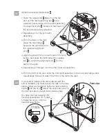

Tip:
Read this entire task before completing any individual steps.
5.1
5.2
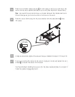
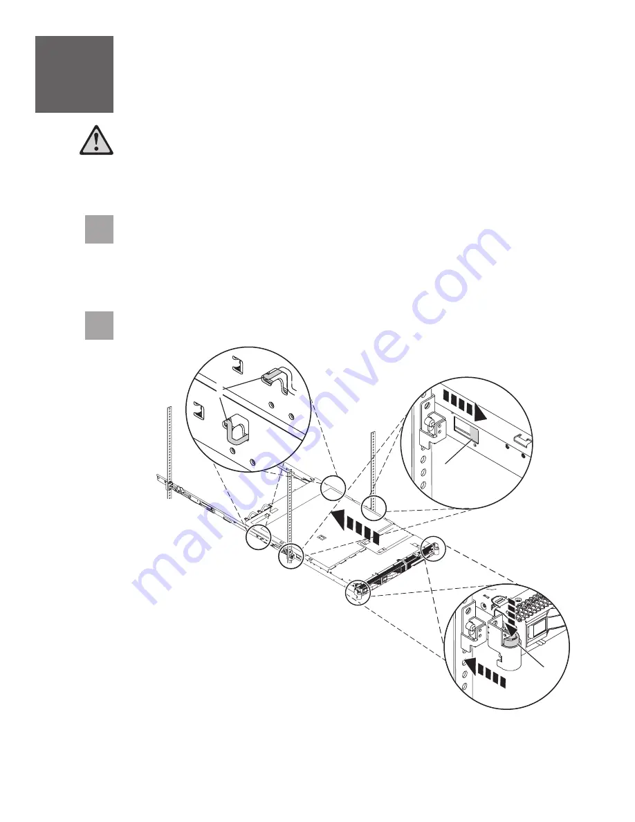
From the front of the rack, align the server on the rails and push the server into
the rack cabinet. If the rail-lock pins
are extended out, pull the side release
latches
toward you, which lifts up the rail-lock pins. Push the server into the
rack the remainder of the way. As you push the server into the rack, the rail-lock
pins extend out and lock into place.
A
B
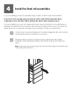
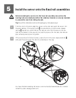
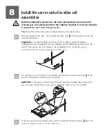
Install the server onto the fixed rail assemblies
5
Before installing the server onto the fixed rail assembly, ensure that the
leveling feet are extended and that the stabilizer bracket is correctly installed
to prevent the rack from falling forward.
If the server does not snap in place, press down on the rack release buttons
and push the server into the rack the remainder of the way.
C
C
B
A
You have finished installing the server onto the fixed rail assemblies. Go to task 6
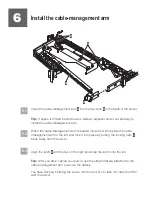
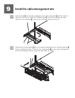
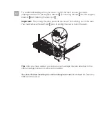
Install the cable-management arm.


