

7.1
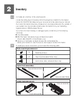
Locate the rack-mounting hardware kit, the cable-management arm, and the slide
rail assemblies that were included with your server.
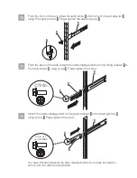
7.3
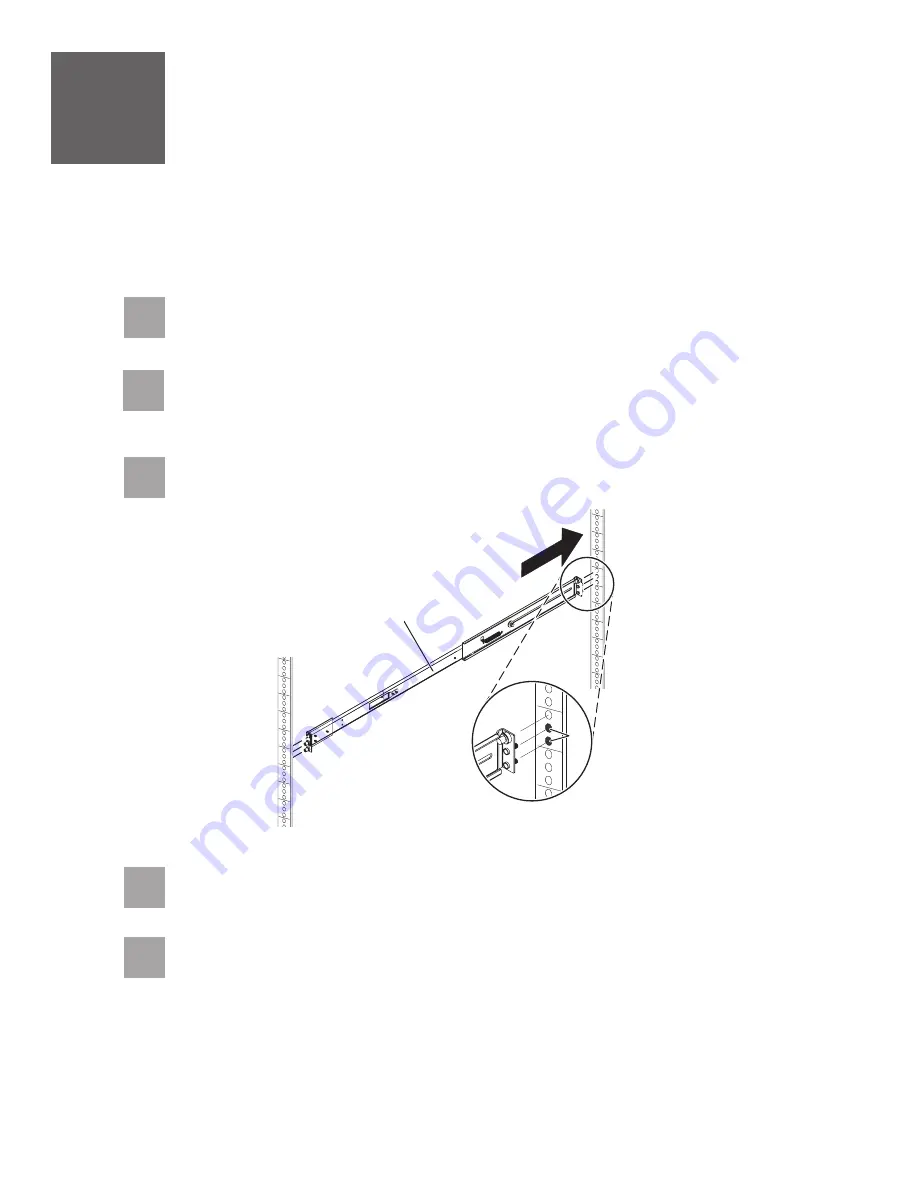
Insert the right slide rail
into the back-right rack mounting flange
holes, with
the rail pins protruding through the flange.
A
B
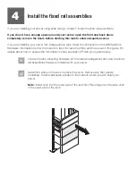
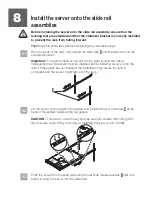
7
Install the slide rail assemblies
If you do not have enough space around your rack to open the front and back doors
completely, remove the doors before starting this task to allow adequate access.
If you are installing your server using fixed rails, go to task 4
Install the fixed rail assemblies.
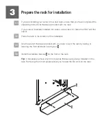
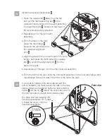
7.2
Determine where in the rack to place the server. Remove any filler panels
necessary to allow adequate access to the location where you will install your
server.
B
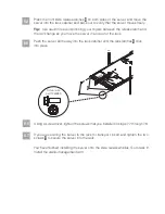
7.4
Press on the end of the slide rail
to compress the spring-loaded mechanism,
and insert the slide rail into the front-right rack mounting flange
holes.
A
B
A
7.5
Repeat steps 7.3 and 7.4 for the left slide rail.


