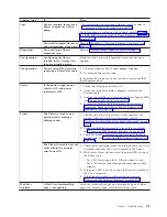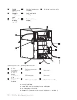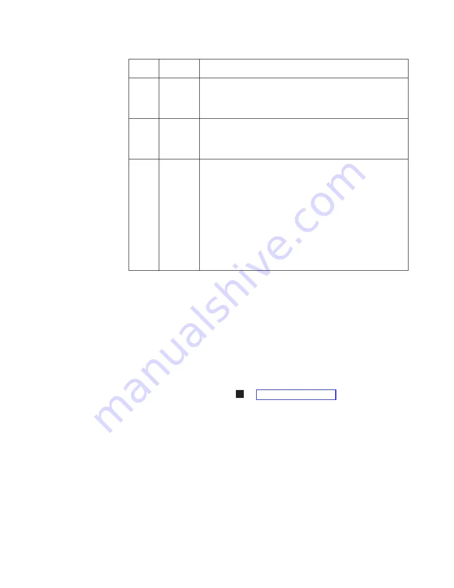
Table
9-5.
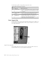
Power
Supply
LEDs
LED
Color
Represents
Power
Supply
Status
Green
AC
OK
(top)
v
Solid
ON
-
The
power
supply’s
AC
input
is
above
the
minimum
requirements
to
operate.
v
Solid
OFF
-
The
power
supply’s
AC
input
is
below
the
minimum
requirements
to
operate.
Green
DC
OK
(middle)
v
Solid
ON
-
The
power
supply’s
output
voltage
is
within
regulation.
v
Solid
OFF
-
The
power
supply’s
output
voltage
is
not
within
regulation.
Blue
Fault
(bottom)
v
Solid
ON
-
Indicates
that
one
of
the
following
faults
has
been
detected:
–
Power
supply
is
outside
of
specifications
–
Current
limit
has
been
exceeded
–
Temperature
limit
has
been
exceeded
–
Fan
failed
while
AC
input
is
present
and
above
the
minimum
operating
voltage
–
AC
input
is
below
the
minimum
operating
voltage
–
The
power
supply
is
ON,
the
Power
button
ON,
but
the
library’s
indicator
panel
is
OFF
v
Solid
OFF
-
Normal:
No
faults
detected
In
the
operator
intervention
associated
with
the
defective
power
supply,
record
both
the
number
of
the
module
and
the
number
of
the
power
supply
connected
to
that
module.
Each
module
can
have
up
to
two
power
supplies.
The
power
supply
on
the
right
is
considered
to
be
#1,
while
the
power
supply
on
the
left
is
#2.
Modules
are
numbered
according
to
their
position
in
relation
to
the
control
module
(CM).
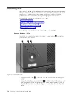
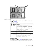
Picker
LED
The
Picker
has
one
green
LED
(
1
in
that
must
be
ON
for
the
Picker
to
function
properly.
If
the
LED
is
not
lit,
the
Picker
assembly
should
be
investigated
for
problems.
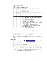
To
observe
the
status
of
the
Picker
LED:
1.
Power
OFF
the
library.
The
Picker
will
move
to
the
bottom
of
the
library.
2.
Open
the
lowest
I/O
Station
door
in
your
library
and,
looking
through
the
opening
to
the
left
of
the
flap
inside
the
I/O
Station,
observe
the
Picker
LED.
Note:
Do
not
open
the
Access
Door
to
observe
the
Picker
LED.
If
the
Access
Door
is
opened,
the
Picker
LED
is
turned
off.
Chapter
9.
Troubleshooting
9-11
Summary of Contents for System Storage TS3310
Page 1: ...IBM System Storage TS3310 Tape Library Setup and Operator Guide GA32 0477 00...
Page 2: ......
Page 3: ...IBM System Storage TS3310 Tape Library Setup and Operator Guide GA32 0477 00...
Page 6: ...iv TS3310 Tape Library Setup and Operator Guide...
Page 12: ...x TS3310 Tape Library Setup and Operator Guide...
Page 14: ...xii TS3310 Tape Library Setup and Operator Guide...
Page 22: ...xx TS3310 Tape Library Setup and Operator Guide...
Page 24: ...xxii TS3310 Tape Library Setup and Operator Guide...
Page 42: ...1 18 TS3310 Tape Library Setup and Operator Guide...
Page 54: ...2 12 TS3310 Tape Library Setup and Operator Guide...
Page 63: ...a66ug019 Figure 3 6 Rails installed in rack front view Chapter 3 Installing the Library 3 9...
Page 78: ...3 24 TS3310 Tape Library Setup and Operator Guide...
Page 86: ...4 8 TS3310 Tape Library Setup and Operator Guide...
Page 98: ...5 12 TS3310 Tape Library Setup and Operator Guide...
Page 106: ...6 8 TS3310 Tape Library Setup and Operator Guide...
Page 220: ...11 22 TS3310 Tape Library Setup and Operator Guide...
Page 226: ...12 6 TS3310 Tape Library Setup and Operator Guide...
Page 236: ...A 10 TS3310 Tape Library Setup and Operator Guide...
Page 240: ...B 4 TS3310 Tape Library Setup and Operator Guide...
Page 266: ...F 8 TS3310 Tape Library Setup and Operator Guide...
Page 273: ......
Page 274: ...Part Number 95P2271 Printed in USA GA32 0477 00 1P P N 95P2271...

