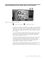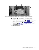
3.
Connect
the
power
supply
by
plugging
in
each
end
of
the
power
cord
in
the
proper
sequence.
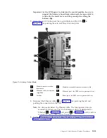
Attention:
First,
connect
the
power
cord
to
the
power
supply
receptacle
(
3
in
Then,
connect
the
power
cord
to
the
power
source.
4.
Perform
Adding
a
Redundant
Power
Supply
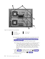
1.
Locate
the
vacant
power
supply
slot
and
remove
the
metal
plate
by
loosening
the
thumb
screws.
2.
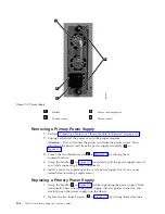
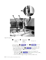
Grasp
the
handle
(
1
in
while
supporting
the
power
supply
from
underneath.
Then,
line
up
the
power
supply
with
the
guides
in
the
slot,
and
carefully
push
the
power
supply
into
the
library.
Note:
Make
sure
you
insert
the
redundant
power
supply
in
the
correct
position,
with
its
on/off
switch
located
at
the
bottom,
below
the
handle.
The
redundant
power
supply
must
be
level
to
slide
into
the
control
module
smoothly.
3.
Tighten
the
thumb
screws
(
2
in
by
turning
them
clockwise.
4.
Plug
in
the
power
cord
to
the
redundant
power
supply
receptacle
(
3
in
5.
Toggle
the
power
switch
(
4
in
to
the
|
(ON)
position.
6.
Check
the
status
of
the
redundant
power
supply’s
LEDs.
The
top
green
LED
and
the
blue
LED
should
remain
solidly
lit
until
the
library
is
powered
on.
7.
Power
on
the
library
using
the
power
button
on
the
front
of
the
machine.
8.
Check
that
status
of
the
redundant
power
supply’s
LEDs,
and
verify
that
the
two
green
LEDs
are
solidly
lit
and
that
the
blue
LED
is
not
lit.
Removing
a
Redundant
Power
Supply
1.
Locate
the
slot
for
the
redundant
power
supply
to
be
removed
on
the
back
of
the
library.
2.
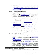
Toggle
the
redundant
power
supply
power
switch
(
4
in
to
the
O
(OFF)
position.
3.
Unplug
the
power
cord
from
the
redundant
power
supply
receptacle
(
3
in
4.
Loosen
the
two
thumb
screws
(
2
in
by
turning
them
counterclockwise.
5.
Grasp
the
handle
(
1
in
and
pull
the
power
supply
toward
you.
Support
the
component
from
underneath
with
your
other
hand.
6.
Install
a
metal
cover
plate
over
the
vacant
redundant
power
supply
slot
if
you
are
not
immediately
installing
a
replacement.
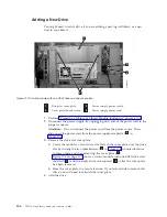
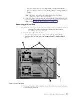
Adding/Removing/Replacing
aDrive
Sled
Tape
drives
mounted
in
sleds
are
installed
into
tape
drive
slots
in
the
rear
of
the
library.
Chapter
11.
Add,
Remove,
Replace
Procedures
11-5
Summary of Contents for System Storage TS3310
Page 1: ...IBM System Storage TS3310 Tape Library Setup and Operator Guide GA32 0477 00...
Page 2: ......
Page 3: ...IBM System Storage TS3310 Tape Library Setup and Operator Guide GA32 0477 00...
Page 6: ...iv TS3310 Tape Library Setup and Operator Guide...
Page 12: ...x TS3310 Tape Library Setup and Operator Guide...
Page 14: ...xii TS3310 Tape Library Setup and Operator Guide...
Page 22: ...xx TS3310 Tape Library Setup and Operator Guide...
Page 24: ...xxii TS3310 Tape Library Setup and Operator Guide...
Page 42: ...1 18 TS3310 Tape Library Setup and Operator Guide...
Page 54: ...2 12 TS3310 Tape Library Setup and Operator Guide...
Page 63: ...a66ug019 Figure 3 6 Rails installed in rack front view Chapter 3 Installing the Library 3 9...
Page 78: ...3 24 TS3310 Tape Library Setup and Operator Guide...
Page 86: ...4 8 TS3310 Tape Library Setup and Operator Guide...
Page 98: ...5 12 TS3310 Tape Library Setup and Operator Guide...
Page 106: ...6 8 TS3310 Tape Library Setup and Operator Guide...
Page 220: ...11 22 TS3310 Tape Library Setup and Operator Guide...
Page 226: ...12 6 TS3310 Tape Library Setup and Operator Guide...
Page 236: ...A 10 TS3310 Tape Library Setup and Operator Guide...
Page 240: ...B 4 TS3310 Tape Library Setup and Operator Guide...
Page 266: ...F 8 TS3310 Tape Library Setup and Operator Guide...
Page 273: ......
Page 274: ...Part Number 95P2271 Printed in USA GA32 0477 00 1P P N 95P2271...

