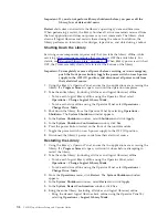
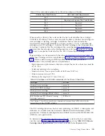
Cartridge
Compatibility
Table
8-1.
Ultrium
data
cartridge
compatibility
with
Ultrium
3
tape
drive
IBM
Ultrium
Tape
Drive
IBM
TotalStorage
LTO
Ultrium
Data
Cartridges
400
GB
(Ultrium
3)
400
GB
WORM
200
GB
(Ultrium
2)
100
GB
(Ultrium
1)
Ultrium
3
Read/Write
Read/Write
Read
only
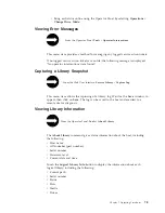
Data
Cartridge
When
processing
tape
in
the
cartridges,
Ultrium
Tape
Drives
use
a
linear,
serpentine
recording
format.
The
Ultrium
3
drive
reads
and
writes
data
on
704
tracks,
sixteen
tracks
at
a
time.
The
first
set
of
tracks
)
is
written
from
near
the
beginning
of
the
tape
to
near
the
end
of
the
tape.
The
head
then
repositions
to
the
next
set
of
tracks
for
the
return
pass.
This
process
continues
until
all
tracks
are
written
and
the
cartridge
is
full,
or
until
all
data
is
written.
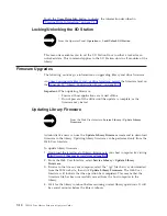
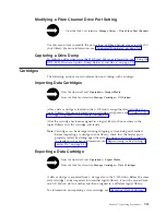
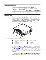
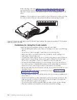
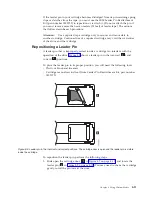
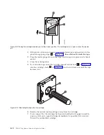
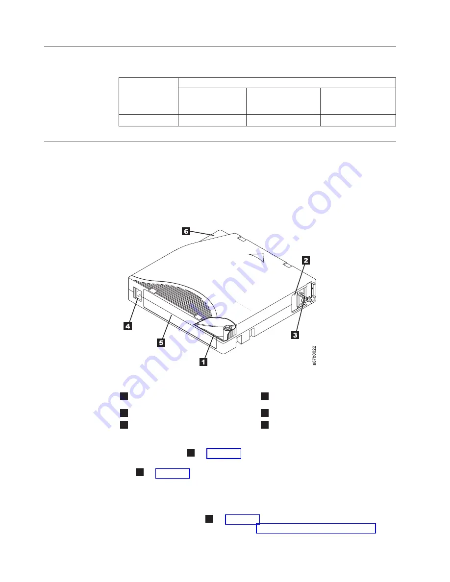
1
LTO
cartridge
memory
(cut-away
view)
4
Write-protect
Switch
2
Cartridge
door
5
Label
area
3
Leader
Pin
6
Insertion
guide
The
cartridge
door
(
2
in
protects
the
tape
from
contamination
when
the
cartridge
is
out
of
the
drive.
Behind
the
door,
the
tape
is
attached
to
a
leader
pin
(
3
in
When
the
cartridge
is
inserted
into
the
drive,
a
threading
mechanism
pulls
the
pin
(and
tape)
out
of
the
cartridge,
across
the
drive
head,
and
onto
a
non-removable
take-up
reel.
The
head
can
then
read
or
write
data
from
or
to
the
tape.
The
write-protect
switch
(
4
in
prevents
data
from
being
written
to
the
tape
cartridge.
For
more
information,
see
Figure
8-1.
The
IBM
TotalStorage
LTO
Ultrium
400
GB
Data
Cartridge
8-2
TS3310
Tape
Library
Setup
and
Operator
Guide
Summary of Contents for System Storage TS3310
Page 1: ...IBM System Storage TS3310 Tape Library Setup and Operator Guide GA32 0477 00...
Page 2: ......
Page 3: ...IBM System Storage TS3310 Tape Library Setup and Operator Guide GA32 0477 00...
Page 6: ...iv TS3310 Tape Library Setup and Operator Guide...
Page 12: ...x TS3310 Tape Library Setup and Operator Guide...
Page 14: ...xii TS3310 Tape Library Setup and Operator Guide...
Page 22: ...xx TS3310 Tape Library Setup and Operator Guide...
Page 24: ...xxii TS3310 Tape Library Setup and Operator Guide...
Page 42: ...1 18 TS3310 Tape Library Setup and Operator Guide...
Page 54: ...2 12 TS3310 Tape Library Setup and Operator Guide...
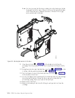
Page 63: ...a66ug019 Figure 3 6 Rails installed in rack front view Chapter 3 Installing the Library 3 9...
Page 78: ...3 24 TS3310 Tape Library Setup and Operator Guide...
Page 86: ...4 8 TS3310 Tape Library Setup and Operator Guide...
Page 98: ...5 12 TS3310 Tape Library Setup and Operator Guide...
Page 106: ...6 8 TS3310 Tape Library Setup and Operator Guide...
Page 220: ...11 22 TS3310 Tape Library Setup and Operator Guide...
Page 226: ...12 6 TS3310 Tape Library Setup and Operator Guide...
Page 236: ...A 10 TS3310 Tape Library Setup and Operator Guide...
Page 240: ...B 4 TS3310 Tape Library Setup and Operator Guide...
Page 266: ...F 8 TS3310 Tape Library Setup and Operator Guide...
Page 273: ......
Page 274: ...Part Number 95P2271 Printed in USA GA32 0477 00 1P P N 95P2271...


