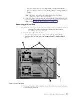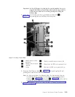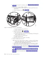
a.
For
a
SCSI
drive,
loosen
the
two
thumb
screws
that
hold
the
SCSI
cable
and
terminator
in
place
by
turning
them
counterclockwise.
Disconnect
the
cable
and
terminator
from
the
drive
being
removed.
b.
For
a
Fibre
Channel
drive,
unplug
the
fibre
cable.
3.
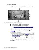
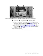
Loosen
the
two
thumb
screws
(
2
in
that
hold
the
drive
in
place
by
turning
them
counterclockwise.
4.
Slide
the
drive
out
of
the
library
module.
Grasp
the
handle
(
5
in
and
slowly
pull
the
drive
toward
you,
while
supporting
the
drive
sled
from
underneath.
Replacing
a
Drive
1.
Align
the
drive
sled
with
the
guide
rails
and
guide
slots
along
the
tracks
(
3
in
and
slowly
slide
the
drive
into
the
library
module,
while
supporting
it
from
underneath.
Attention:
If
the
drive
has
a
tape
in
it,
remove
the
tape
before
installing
the
drive
in
you
library.
2.
Tighten
the
two
thumb
screws
(
2
in
that
hold
the
drive
in
place
by
turning
them
clockwise.
3.
Reconnect
the
drive
sled
cable.
a.
For
a
SCSI
drive
sled,
plug
the
cable
and
terminator
into
the
drive
sled.
Tighten
the
thumb
screws
that
hold
the
SCSI
cable
and
terminator
in
place
by
turning
them
clockwise.
Attention:
Visually
inspect
the
connectors
on
the
SCSI
cable
before
installing
it.
If
the
cable
or
terminator
connector
has
bent
pins,
replace
the
part.
b.
For
a
Fibre
Channel
drive
sled,
connect
the
fibre
cable.
Attention:
Fibre
Channel
connections
have
no
terminator
and
require
a
different
type
of
plug.
Each
plug
is
connected
to
the
Fibre
network
through
a
separate
cable.
Check
the
cable
for
possible
damages
such
as
scratches
which
have
damaged
the
cable
insolation.
If
the
cable
is
damaged,
replace
it
to
avoid
possible
connection
problems.
Ensure
that
the
fibre
connector
is
securely
locked
in
the
socket
of
the
drive.
You
can
hear
a
″
click
″
when
the
connector
is
securely
installed.
4.
Vary
the
drives
online.
v
From
the
Operator
Panel,
select
Operation
→
Change
Drive
Mode
.
v
From
the
Web
User
Interface,
select
Manage
Drives
→
Change
State
of
Drives
.
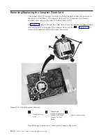
Removing/Replacing
the
Library
Control
Blade
and
Compact
Flash
Card
The
Library
Control
Blade
(LCB)
manages
the
entire
library,
including
the
Operator
Panel
and
picker
assembly.
It
also
runs
system
tests
to
ensure
that
the
library
is
functioning
properly.
11-10
TS3310
Tape
Library
Setup
and
Operator
Guide
Summary of Contents for System Storage TS3310
Page 1: ...IBM System Storage TS3310 Tape Library Setup and Operator Guide GA32 0477 00...
Page 2: ......
Page 3: ...IBM System Storage TS3310 Tape Library Setup and Operator Guide GA32 0477 00...
Page 6: ...iv TS3310 Tape Library Setup and Operator Guide...
Page 12: ...x TS3310 Tape Library Setup and Operator Guide...
Page 14: ...xii TS3310 Tape Library Setup and Operator Guide...
Page 22: ...xx TS3310 Tape Library Setup and Operator Guide...
Page 24: ...xxii TS3310 Tape Library Setup and Operator Guide...
Page 42: ...1 18 TS3310 Tape Library Setup and Operator Guide...
Page 54: ...2 12 TS3310 Tape Library Setup and Operator Guide...
Page 63: ...a66ug019 Figure 3 6 Rails installed in rack front view Chapter 3 Installing the Library 3 9...
Page 78: ...3 24 TS3310 Tape Library Setup and Operator Guide...
Page 86: ...4 8 TS3310 Tape Library Setup and Operator Guide...
Page 98: ...5 12 TS3310 Tape Library Setup and Operator Guide...
Page 106: ...6 8 TS3310 Tape Library Setup and Operator Guide...
Page 220: ...11 22 TS3310 Tape Library Setup and Operator Guide...
Page 226: ...12 6 TS3310 Tape Library Setup and Operator Guide...
Page 236: ...A 10 TS3310 Tape Library Setup and Operator Guide...
Page 240: ...B 4 TS3310 Tape Library Setup and Operator Guide...
Page 266: ...F 8 TS3310 Tape Library Setup and Operator Guide...
Page 273: ......
Page 274: ...Part Number 95P2271 Printed in USA GA32 0477 00 1P P N 95P2271...

