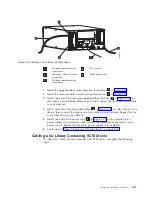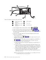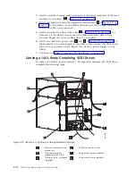
1.
Install
a
module
communication
terminator
in
the
upper
receptacle
of
the
upper
module
of
your
library
(
4
in
2.
Install
one
end
of
the
module-to-module
communication
cable
(
2
in
in
the
lower
receptacle
of
the
upper
module
of
your
library,
then
install
the
other
end
in
the
upper
receptacle
of
the
lower
module
of
your
library.
3.
Install
a
module
communication
terminator
in
the
lower
receptacle
of
the
lower
module
of
your
library
(
1
in
4.
Install
one
end
of
the
customer-supplied
Ethernet
cable
(
3
in
in
the
Library
Control
Blade
Ethernet
port,
then
connect
the
other
end
of
the
cable
to
your
network.
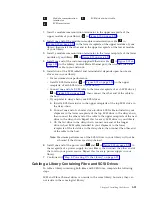
5.
For
SCSI
drives,
installation
of
the
SCSI
cable(s)
and
terminator(s)
depends
upon
how
many
drives
are
in
your
library.
v
For
maximum
drive
performance:
v
Install
a
SCSI
terminator
(
5
in
in
the
upper
receptacle
of
each
SCSI
drive
in
your
library.
v
Connect
one
end
of
a
SCSI
cable
to
the
lower
receptacle
of
each
SCSI
drive
(
6
in
then
connect
the
other
end
of
the
cable
to
the
host.
v
If
you
prefer
to
daisy-chain
your
SCSI
drives:
a.
Install
a
SCSI
terminator
in
the
upper
receptacle
of
the
top
SCSI
drive
in
the
daisy-chain.
b.
Connect
one
end
of
a
shorter
drive-to-drive
SCSI
cable
included
in
your
shipment
to
the
lower
receptacle
of
the
top
SCSI
drive
in
the
daisy-chain,
then
connect
the
other
end
of
the
cable
to
the
upper
receptacle
of
the
next
drive
in
the
daisy-chain.
Repeat
this
for
every
SCSI
drive
in
your
library.
c.
On
the
last
drive
in
the
daisy-chain,
connect
one
end
of
the
longer
drive-to-host
SCSI
cable
included
in
your
shipment
to
the
lower
receptacle
of
the
last
drive
in
the
daisy-chain,
then
connect
the
other
end
of
the
cable
to
the
host.
Note:
Maximum
performance
of
the
SCSI
drives
in
your
library
will
not
be
achieved
if
the
drives
are
daisy-chained.
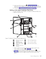
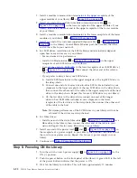
6.
For
Fibre
drives:
v
Install
one
end
of
the
drive
fibre
cable
(
7
in
in
a
fibre
drive
in
the
library,
then
connect
the
other
end
of
the
cable
to
your
network.
Repeat
this
for
every
fibre
drive
in
your
library.
7.
Install
one
end
of
the
power
cord
(
7
and
8
in
in
the
receptacle
of
a
power
supply
in
your
library,
then
connect
the
other
end
of
the
cord
to
your
power
source.
Repeat
this
for
every
power
supply
in
your
library.
8.
Continue
with
Step
5:
Powering
ON
the
Library
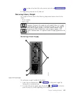
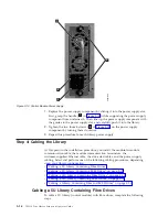
1.
Turn
the
switch
on
each
power
supply
(
4
in
to
the
ON
(|)
position.
2.
Push
the
power
button
on
the
front
panel
of
the
library.
A
green
LED
to
the
left
of
the
power
button
indicates
that
the
power
is
ON.
3.
Wait
for
the
library
to
initialize.
This
will
take
approximately
10
minutes.
3-22
TS3310
Tape
Library
Setup
and
Operator
Guide
Summary of Contents for System Storage TS3310
Page 1: ...IBM System Storage TS3310 Tape Library Setup and Operator Guide GA32 0477 00...
Page 2: ......
Page 3: ...IBM System Storage TS3310 Tape Library Setup and Operator Guide GA32 0477 00...
Page 6: ...iv TS3310 Tape Library Setup and Operator Guide...
Page 12: ...x TS3310 Tape Library Setup and Operator Guide...
Page 14: ...xii TS3310 Tape Library Setup and Operator Guide...
Page 22: ...xx TS3310 Tape Library Setup and Operator Guide...
Page 24: ...xxii TS3310 Tape Library Setup and Operator Guide...
Page 42: ...1 18 TS3310 Tape Library Setup and Operator Guide...
Page 54: ...2 12 TS3310 Tape Library Setup and Operator Guide...
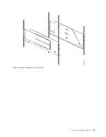
Page 63: ...a66ug019 Figure 3 6 Rails installed in rack front view Chapter 3 Installing the Library 3 9...
Page 78: ...3 24 TS3310 Tape Library Setup and Operator Guide...
Page 86: ...4 8 TS3310 Tape Library Setup and Operator Guide...
Page 98: ...5 12 TS3310 Tape Library Setup and Operator Guide...
Page 106: ...6 8 TS3310 Tape Library Setup and Operator Guide...
Page 220: ...11 22 TS3310 Tape Library Setup and Operator Guide...
Page 226: ...12 6 TS3310 Tape Library Setup and Operator Guide...
Page 236: ...A 10 TS3310 Tape Library Setup and Operator Guide...
Page 240: ...B 4 TS3310 Tape Library Setup and Operator Guide...
Page 266: ...F 8 TS3310 Tape Library Setup and Operator Guide...
Page 273: ......
Page 274: ...Part Number 95P2271 Printed in USA GA32 0477 00 1P P N 95P2271...

