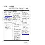
Table 1. Features and specifications (continued)
Size:
v
2U chassis:
– Depth: 55.8 cm (22.0 inches)
– Width (EIA flange to EIA flange outer
edge): 48.6 cm (19.1 inches)
– Height: 8.72 cm (3.43 inches)
– Weight (with 2 system-board trays):
21.4 kg (47.2 lb)
– Weight (GPGPU server without
add-on adapters): 18.1 kg (39.9 lbs)
v
1U node:
– Depth: 51.8 cm (20.4 inches)
– Width (cam lever tip-to-tip): 47.1 cm
(18.6 inches)
– Height: 4.19 cm (1.65 inches)
Power supply:
v
Maximum of two hot-swap power
supplies for redundancy support
– 550-watt ac
– 750-watt ac
– 900-watt ac
Note:
Power supplies in the server must
be with the same power rating or wattage.
Integrated functions:
v
Integrated Management Module II
(IMM2), which consolidates multiple
management functions in a single
chip.
v
Intel Powerville I350 Gb Ethernet
controller with Wake on LAN support
v
Five Universal Serial Bus (USB) 2.0
ports (four front of the chassis, and
one embedded hypervisor software is
installed)
v
Two ethernet ports
v
One System Management RJ-45 on
the front to connect to a systems
management network. This system
management connector is dedicated
to the IMM2 functions.
v
One serial port
Predictive Failure Analysis (PFA)
alerts:
v
Memory
Electrical input:
v
Sine-wave input (50 - 60 Hz) required
v
Input voltage low range:
– Minimum: 100 V ac
– Maximum: 127 V ac
v
Input voltage high range:
– Minimum: 200 V ac
– Maximum: 240 V ac
v
Input kilovolt-amperes (kVA),
approximately:
– Minimum: 0.150 kVA
– Maximum: 1.148 kVA
Notes:
1. Power consumption and heat output
vary depending on the number and type
of optional features installed and the
power-management optional features in
use.
2. The noise emission level stated is the
declared (upper limit) sound power
level, in bels, for a random sample of
machines. All measurements are made
in accordance with ISO 7779 and
reported in conformance with ISO 9296.
Server controls, LEDs, and power
This section describes the controls and light-emitting diodes (LEDs) and how to turn
the server on and off.
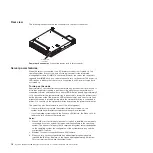
Front view
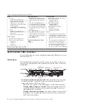
The following illustration shows the controls, connectors, and LEDs on the front of
the server. The operator panel on the system-board tray is the same for all server
configurations.
Power-on LED/
power button
Locator LED
Hard disk drive
activity LED
System-error LED
USB
Ethernet
Ethernet link
activity/status LED
Ethernet connection
Speed LED
Systems-management
Ethernet
Serial Video
Dual-port
network adapter
(Optional)
PCI slot 2
PCI slot 1
v
Power-control button and power-on LED:
Press this button to turn the server
on and off manually or to wake the server from a reduced-power state. The
states of the power-on LED are as follows:
Off:
Power is not present or the power supply, or the LED itself has failed.
Flashing rapidly (4 times per second):
The server is turned off and is not
ready to be turned on. The power-control button is disabled. This will last
approximately 20 to 40 seconds.
Flashing slowly (once per second):
The server is turned off and is ready to
be turned on. You can press the power-control button to turn on the server.
Lit:
The server is turned on.
8
System x iDataPlex dx360 M4 Types 7912 and 7913: Problem Determination and Service Guide
Summary of Contents for System x iDataPlex dx360 M4 7912
Page 1: ...System x iDataPlex dx360 M4 Types 7912 and 7913 Problem Determination and Service Guide...
Page 2: ......
Page 3: ...System x iDataPlex dx360 M4 Types 7912 and 7913 Problem Determination and Service Guide...
Page 22: ...4 System x iDataPlex dx360 M4 Types 7912 and 7913 Problem Determination and Service Guide...
Page 278: ...260 System x iDataPlex dx360 M4 Types 7912 and 7913 Problem Determination and Service Guide...
Page 292: ...274 System x iDataPlex dx360 M4 Types 7912 and 7913 Problem Determination and Service Guide...
Page 392: ...374 System x iDataPlex dx360 M4 Types 7912 and 7913 Problem Determination and Service Guide...
Page 399: ......
Page 400: ...Part Number 46W8218 Printed in USA 1P P N 46W8218...

