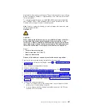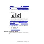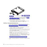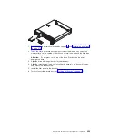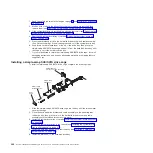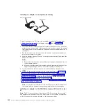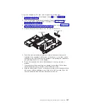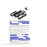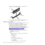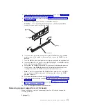
2. Make a note of where cables are attached to the adapter; then, disconnect the
cables.
3. (If you are moving an adapter from the GPGPU enclosure, skip this step)
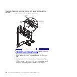
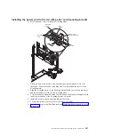
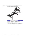
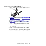
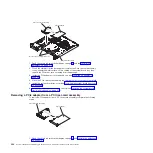
Remove a PCIe riser-card assembly from the system-board tray (see
“Removing a PCIe riser-card assembly from the system-board tray” on page
302).
4. Pull the adapter out of the connector on the PCIe riser-card assembly.
Note:
Make sure that the adapter is pulled out carefully. Improper removal of
the adapter might damage the PCIe riser-card assembly or the adapter.
5. If you are instructed to return the adapter, follow all packaging instructions, and
use any packaging materials for shipping that are supplied to you.
Installing an adapter
Important:
The maximum power consumption from all supply voltages for a single
PCIe slot is the same as specified in PCI Local Bus Specification Revision 2.3 for
conventional slots.
To ensure that an adapter works correctly in your uEFI-based server, make sure
that the adapter firmware is at the latest level.
Important:
Some cluster solutions require specific code levels or coordinated code
updates. If the device is part of a cluster solution, verify that the latest level of code
is supported for the cluster solution before you update the code.
Note:
All General Purpose Graphics Processing Unit (GPGPU) adapters installed
in the server must be the same. They must be identical in brand and type. When
you install additional GPGPUs, make sure you purchase GPGPUs with the same
product part number as shown on the existing GPGPUs in the server.
The following notes describe the types of adapters that the server supports and
other information that you must consider when you install an adapter:
v
Locate the documentation that comes with the adapter and follow those
instructions in addition to the instructions in this section.
v
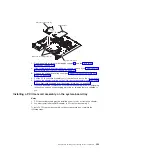
The server provides two PCI riser-card slots on the system board. For
configuration information, see the ServeRAID documentation at
http://www.ibm.com/supportportal/.
Chapter 5. Removing and replacing server components
305
Summary of Contents for System x iDataPlex dx360 M4 7912
Page 1: ...System x iDataPlex dx360 M4 Types 7912 and 7913 Problem Determination and Service Guide...
Page 2: ......
Page 3: ...System x iDataPlex dx360 M4 Types 7912 and 7913 Problem Determination and Service Guide...
Page 22: ...4 System x iDataPlex dx360 M4 Types 7912 and 7913 Problem Determination and Service Guide...
Page 278: ...260 System x iDataPlex dx360 M4 Types 7912 and 7913 Problem Determination and Service Guide...
Page 292: ...274 System x iDataPlex dx360 M4 Types 7912 and 7913 Problem Determination and Service Guide...
Page 392: ...374 System x iDataPlex dx360 M4 Types 7912 and 7913 Problem Determination and Service Guide...
Page 399: ......
Page 400: ...Part Number 46W8218 Printed in USA 1P P N 46W8218...

