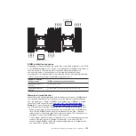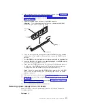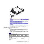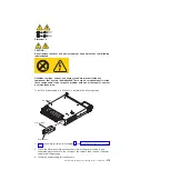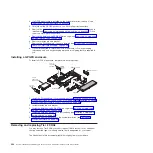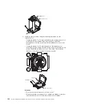
Handle
Installation tool
v
If using Installation Tool B,
1
lift the interlock latch and hold it up while
you
2
twist the microprocessor installation tool handle counterclockwise
to the open position, and then release the interlock latch. The following
illustration of the installation tool shows the location of the interlock latch
and counterclockwise rotation of the handle before loading the
microprocessor.
H
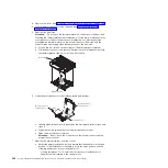
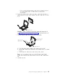
b. Align the installation tool with the screws, as shown in the following graphic,
and lower the installation tool on the microprocessor. The installation tool
rests flush on the socket only when it is aligned correctly.
Installation tool
Microprocessor
Alignment
pins
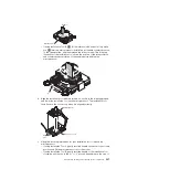
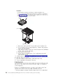
c. Using the following instructions for your installation tool to remove the
microprocessor.
v
If using Installation Tool A, gently twist the handle clockwise to the closed
position and lift the microprocessor out of the socket.
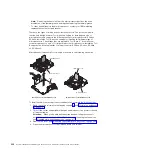
v
If using Installation Tool B, gently twist the handle of the installation tool
clockwise until it locks in the “H” or “L” position, depending on the size of
Chapter 5. Removing and replacing server components
327
Summary of Contents for System x iDataPlex dx360 M4 7912
Page 1: ...System x iDataPlex dx360 M4 Types 7912 and 7913 Problem Determination and Service Guide...
Page 2: ......
Page 3: ...System x iDataPlex dx360 M4 Types 7912 and 7913 Problem Determination and Service Guide...
Page 22: ...4 System x iDataPlex dx360 M4 Types 7912 and 7913 Problem Determination and Service Guide...
Page 278: ...260 System x iDataPlex dx360 M4 Types 7912 and 7913 Problem Determination and Service Guide...
Page 292: ...274 System x iDataPlex dx360 M4 Types 7912 and 7913 Problem Determination and Service Guide...
Page 392: ...374 System x iDataPlex dx360 M4 Types 7912 and 7913 Problem Determination and Service Guide...
Page 399: ......
Page 400: ...Part Number 46W8218 Printed in USA 1P P N 46W8218...

