


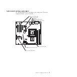
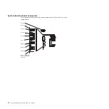

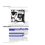

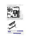
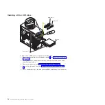
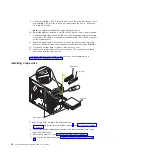
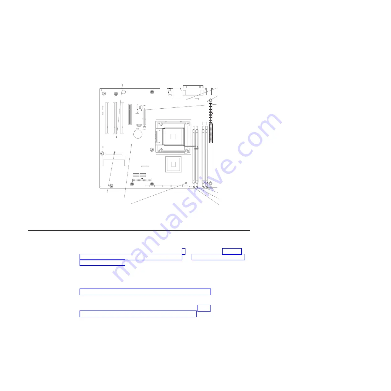
System-board
LEDs
The
following
illustration
shows
the
light-emitting
diodes
(LEDs)
on
the
system
board.
Standby power LED
System fan error LED
Microprocessor
fan error LED
mini-BMC heartbeat LED
VRD power fault LED
System power LED
DASD fan error LED
DIMM 1 error LED
DIMM 2 error LED
DIMM 3 error LED
DIMM 4 error LED
For
more
information
about
the
system-board
LEDs,
see
the
Problem
Determination
and
Service
Guide
on
the
IBM
System
x
Documentation
CD.
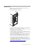
Installation
guidelines
Before
you
install
optional
devices,
read
the
following
information:
v
Read
the
safety
information
that
begins
on
page
the
guidelines
in
and
This
information
will
help
you
work
safely.
v
When
you
install
your
new
server,
take
the
opportunity
to
download
and
apply
the
most
recent
firmware
updates.
This
step
will
help
to
ensure
that
any
known
issues
are
addressed
and
that
your
server
is
ready
to
function
at
maximum
levels
of
performance.
To
download
firmware
updates
for
your
server,
go
to
http://www.ibm.com/servers/eserver/support/xseries/index.html/,
select
System
4362
or
4363
from
the
Hardware
list,
click
Go,
and
then
click
the
Download
tab.
For
additional
information
about
tools
for
updating,
managing,
and
deploying
firmware,
see
the
System
x
and
xSeries
Tools
Center
at
publib.boulder.ibm.com/infocenter/toolsctr/v1r0/index.jsp
v
Before
you
install
optional
hardware
devices,
make
sure
that
the
server
is
working
correctly.
Start
the
server,
and
make
sure
that
the
operating
system
starts,
if
an
operating
system
is
installed,
or
that
a
19990305
error
code
is
displayed,
indicating
that
an
operating
system
was
not
found
but
the
server
is
otherwise
working
correctly.
If
the
server
is
not
working
correctly,
see
"Solving
Problems"
in
the
Installation
Guide
for
diagnostic
information.
v
Observe
good
housekeeping
in
the
area
where
you
are
working.
Place
removed
covers
and
other
parts
in
a
safe
place.
18
System
x3200
Types
4362
and
4363:
User’s
Guide
Summary of Contents for System x3200 4362
Page 1: ...System x3200 Types 4362 and 4363 User s Guide...
Page 2: ......
Page 3: ...System x3200 Types 4362 and 4363 User s Guide...
Page 81: ...Web site continued Update Xpress program 7 weight 3 Index 67...
Page 82: ...68 System x3200 Types 4362 and 4363 User s Guide...
Page 83: ......
Page 84: ...Part Number 42D2453 Printed in USA 1P P N 42D2453...