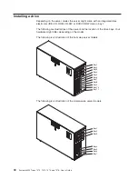

Installing
a
hot-swap
hard
disk
drive
Some
server
models
come
with
hot-swap
SAS
or
SATA
hot-swap
hard
disk
drives.
Before
you
install
a
hot-swap
hard
disk
drive,
read
the
following
information:
v
The
hot-swap
drives
must
be
either
all
SAS
hard
disk
drives
or
all
SATA
hard
disk
drives;
do
not
mix
SAS
and
SATA
drives.
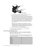
v
The
sequence
for
installing
the
hard
disk
drives
is
to
install
the
drives
starting
from
the
top
bay
(bay
4)
and
go
down
to
the
bottom
bay
(bay
11).
v
Inspect
the
drive
tray
for
signs
of
damage.
v
Make
sure
that
the
drive
is
correctly
installed
in
the
tray.
v
You
do
not
have
to
turn
off
the
server
to
install
hot-swap
drives
in
the
hot-swap
drive
bays.
v
All
hot-swap
drives
must
have
the
same
throughput
speed
rating;
mixing
speed
ratings
might
cause
all
drives
to
operate
at
the
lower
throughput
speed.
v
The
drive
ID
for
each
hot-swap
hard
disk
drive
is
printed
on
the
bezel.
v
If
you
want
to
install
the
maximum
number
of
hot-swap
drives
(eight),
you
must
order
the
4-drive
backplane
option
kit.
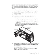
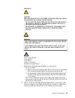
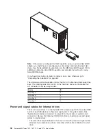
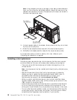
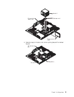
Attention:
When
you
install
the
optional
4-drive
backplane
option
kit
to
upgrade
to
eight
drives,
make
sure
that
you
remove
the
dust
shield
(if
one
is
present)
from
the
hot-swap
SAS/SATA
signal
connector
on
the
system
board.
Carefully
grasp
the
dust
shield
and
pull
it
out
of
the
signal
connector.
v
To
maintain
proper
system
cooling,
do
not
operate
the
server
for
more
than
10
minutes
without
either
a
drive
or
a
filler
panel
installed
in
each
drive
bay.
Attention:
Static
electricity
that
is
released
to
internal
server
components
when
the
server
is
powered-on
might
cause
the
server
to
stop,
which
could
result
in
the
loss
of
data.
To
avoid
this
potential
problem,
always
use
an
electrostatic-discharge
wrist
strap
or
other
grounding
system
when
working
inside
the
server
with
the
power
on.
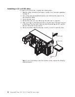
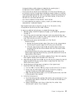
To
install
a
hot-swap
hard
disk
drive,
complete
the
following
steps:
1.
Read
the
safety
information
that
begins
on
page
v
and
“Installation
guidelines”
on
page
22.
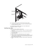
2.
Unlock
the
side
cover.
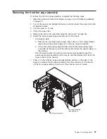
3.
Remove
the
side
cover
(see
“Removing
the
side
cover”
on
page
26.
4.
Place
your
finger
on
the
depression
area
on
the
left
side
of
the
bezel
door
and
rotate
it
away
from
the
server.
After
you
rotate
the
bezel
beyond
90°,
pull
the
bezel
off
the
server
and
set
it
aside.
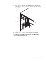
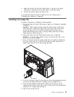
5.
Remove
the
EMC
shield
from
the
bay
in
which
you
want
to
install
the
drive.
6.
Touch
the
static-protective
package
that
contains
the
drive
to
any
unpainted
metal
surface
on
the
server;
then,
remove
the
drive
from
the
package
and
place
it
on
a
static-protective
surface.
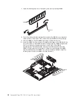
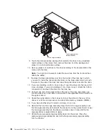
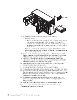
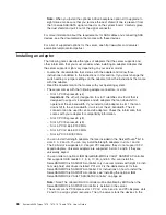
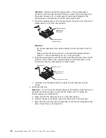
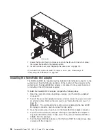
7.
Install
the
hard
disk
drive
in
the
hot-swap
bay:
a.
Make
sure
that
the
drive
tray
handle
is
open.
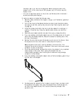
b.
Align
the
drive
assembly
with
the
guide
rails
in
the
bay.
Chapter
2.
Installing
options
41
Summary of Contents for System x3400 Type 7975
Page 1: ...System x3400 Types 7973 7974 7975 and 7976 User s Guide...
Page 2: ......
Page 3: ...System x3400 Types 7973 7974 7975 and 7976 User s Guide...
Page 88: ...74 System x3400 Types 7973 7974 7975 and 7976 User s Guide...
Page 126: ...112 System x3400 Types 7973 7974 7975 and 7976 User s Guide...
Page 133: ......
Page 134: ...Part Number 44W2584 Printed in USA 1P P N 44W2584...


