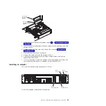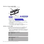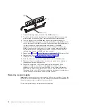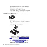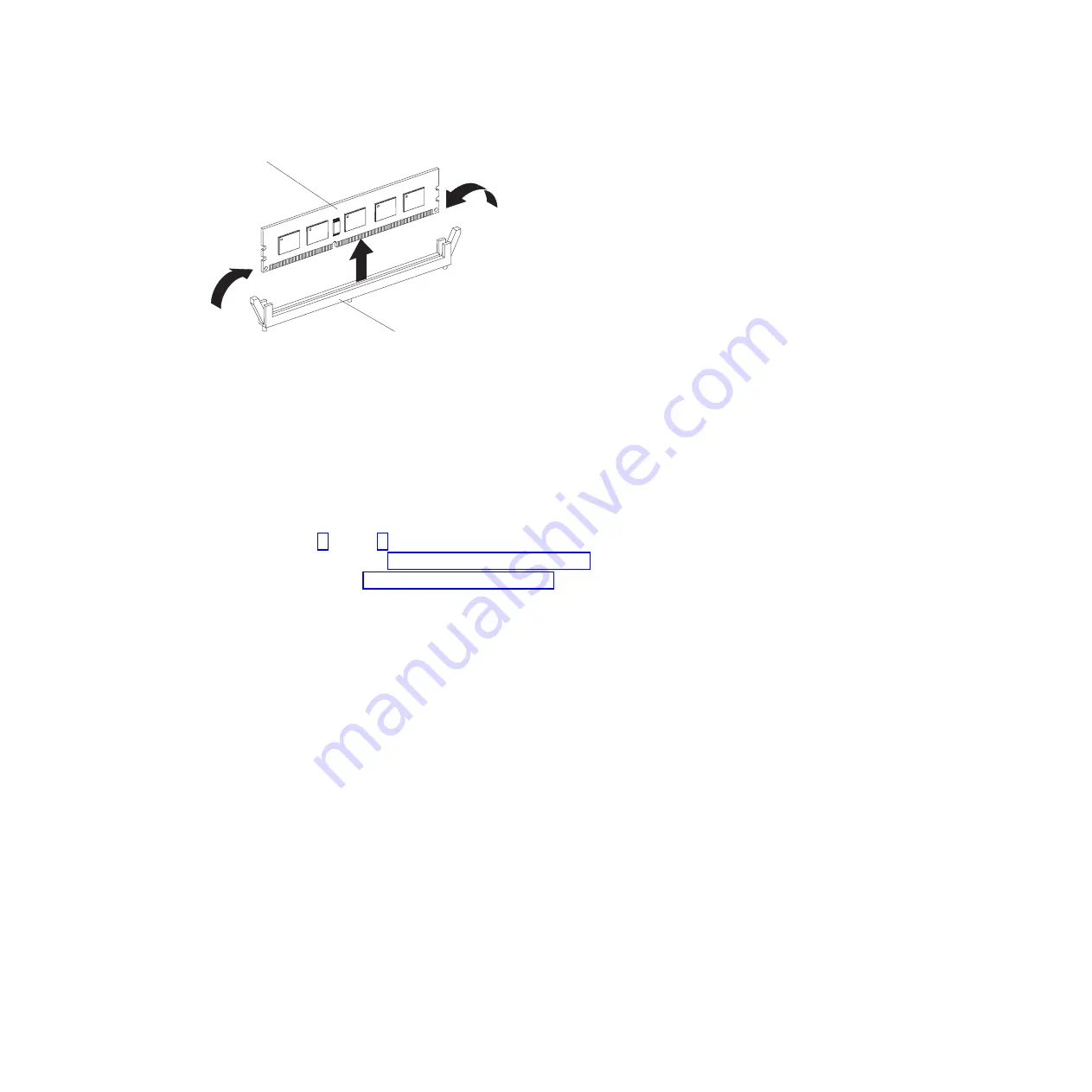
DIMM
DIMM connector
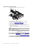
1. Open the retaining clip on each end of the DIMM connector.
2. Touch the static-protective package that contains the DIMM to any unpainted
metal surface on the server. Then, remove the DIMM from the package.
3. Turn the DIMM so that the DIMM keys align correctly with the connector.
4. Insert the DIMM into the connector by aligning the edges of the DIMM with the
slots at the ends of the DIMM connector. Firmly press the DIMM straight down
into the connector by applying pressure on both ends of the DIMM
simultaneously. The retaining clips snap into the locked position when the
DIMM is firmly seated in the connector. If there is a gap between the DIMM
and the retaining clips, the DIMM has not been correctly inserted; open the
retaining clips, remove the DIMM, and then reinsert it.
5. Repeat steps 1 through 4 until all the new or replacement DIMMs are installed.
6. Replace the air duct (see “Installing the air duct” on page 48).
7. Install the cover (see “Installing the cover” on page 46).
8. Slide the server into the rack and tighten the rack release thumbscrews.
9. Reconnect the external cables; then, reconnect the power cords and turn on
the peripheral devices and the server.
10. Check the system-error LED on the operator information panel. If the
system-error LED is off, you have completed this procedure. If the
system-error LED is on, look at the other LEDs on the operator information
panel and the LEDs on the system board; an error LED (amber) that is lit on
the system board or an LED on the hard disk drive backplane or system board
that is off when it should be on can help isolate the error.
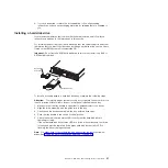
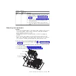
Removing a power supply
Important:
If the server has two power supplies and you remove either of them, the
server will not have redundant power; if the server power load then exceeds 600 W,
the server might not start or might not function correctly.
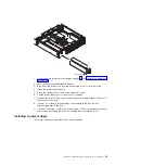
To remove a power supply, complete the following steps.
54
IBM System x3610 Type 7942: Problem Determination and Service Guide
Summary of Contents for System x3610
Page 1: ...IBM System x3610 Type 7942 Problem Determination and Service Guide...
Page 2: ......
Page 3: ...IBM System x3610 Type 7942 Problem Determination and Service Guide...
Page 8: ...vi IBM System x3610 Type 7942 Problem Determination and Service Guide...
Page 32: ...14 IBM System x3610 Type 7942 Problem Determination and Service Guide...
Page 54: ...36 IBM System x3610 Type 7942 Problem Determination and Service Guide...
Page 143: ......
Page 144: ...Part Number 49Y0084 Printed in USA 1P P N 49Y0084...

