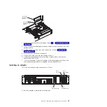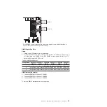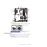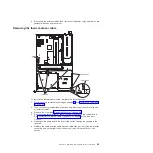
Microprocessor 2
connector
Microprocessor 1
connector
SAS
channel B
SAS
channel A
SATA 0
Battery
connector
lot 1
S
PCI 33 MHz
Slot 3 PCI Express x8
DIMM 6
DIMM 5
DIMM 4
DIMM 3
DIMM 2
DIMM 1
IPMB
connector
lot
S
2 PCI 33 MHz
Slot 4 PCI Express x8
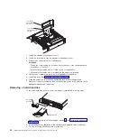
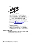
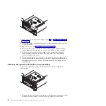
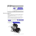
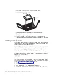
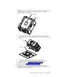
9. Remove the battery:
a. Use a fingernail to press the top of the battery clip away from the battery.
The battery pops up when released.
b. Use your thumb and index finger to lift the battery from the socket.
10. Dispose of the battery as required by local ordinances or regulations. See
“Battery return program” on page 118 for more information.
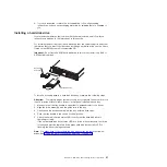
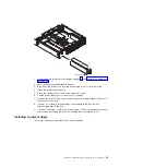
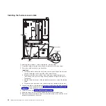
Installing the battery
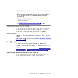
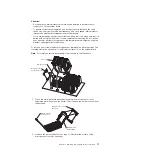
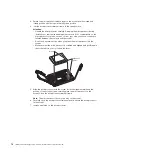
The following notes describe information that you must consider when replacing the
battery in the server.
v
After you replace the battery, you must reconfigure the server and reset the
system date and time.
v
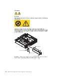
To avoid possible danger, read and follow the following safety statement.
Chapter 4. Removing and replacing server components
59
Summary of Contents for System x3610
Page 1: ...IBM System x3610 Type 7942 Problem Determination and Service Guide...
Page 2: ......
Page 3: ...IBM System x3610 Type 7942 Problem Determination and Service Guide...
Page 8: ...vi IBM System x3610 Type 7942 Problem Determination and Service Guide...
Page 32: ...14 IBM System x3610 Type 7942 Problem Determination and Service Guide...
Page 54: ...36 IBM System x3610 Type 7942 Problem Determination and Service Guide...
Page 143: ......
Page 144: ...Part Number 49Y0084 Printed in USA 1P P N 49Y0084...

